Piezoelectric composite component electrode manufacturing method

A technology of piezoelectric composites and components, applied in the manufacture/assembly of electrical components, piezoelectric/electrostrictive devices, piezoelectric/electrostrictive/magnetostrictive devices, etc., can solve polymer deformation and destroy piezoelectric Composite components, carbonization and other problems, to achieve the effect of strong weldability, high bonding strength and low electrode resistance

Active Publication Date: 2018-05-22
DALIAN UNIV OF TECH
View PDF3 Cites 2 Cited by
  • Summary
  • Abstract
  • Description
  • Claims
  • Application Information

AI Technical Summary

Problems solved by technology

However, since the working temperature of the polymer in the piezoelectric composite element is generally lower than 150°C, the high-temperature process of the back-silver process will lead to deterioration of the polymer such as deformation and carbonization, and damage the piezoelectric composite element.

Method used


Image

  • Piezoelectric composite component electrode manufacturing method
  • Piezoelectric composite component electrode manufacturing method

Examples


Embodiment 1

[0020] The specific implementation steps of embodiment 1 are as follows:

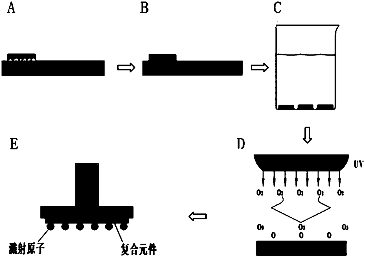
[0021] 1) Surface treatment of PZT piezoelectric composite components

[0022] The size of the PZT piezoelectric composite element in this embodiment is 10mm×10mm×3mm (length×width×thickness). Carry out in the following order: Grind it with an automatic pressure grinding and polishing machine, the rotation speed is 50rpm, and the grinding time is 40min, so that the surface flatness and roughness are lower than 1μm and 800nm ​​respectively; PZT piezoelectric composite elements are put into Acetone, absolute ethanol, and deionized water were ultrasonically cleaned at room temperature for 20 minutes to remove dust and impurities attached to the surface; put in a degreasing solution at 40°C for 10 minutes to remove saponified oil and mineral oil on the surface; Dry in an oven at 60°C for 35 minutes;

[0023] 2) Surface modification of PZT piezoelectric composite elements

[0024] The surface of the PZT c...

Embodiment 2

[0027] In embodiment 2, the output power to the surface modification of PZT composite element in step 2) is 12mW / cm2, the ultraviolet irradiation time 5min; Step 3) in the sputtering Ti electrode layer time is 12min, sputtering Cu electrode layer time 40min, and the time for sputtering the Ag electrode layer was 15min; other conditions were the same as in Example 1.

Embodiment 3

[0028] In embodiment 3, the output power to the surface modification of PZT composite element in step 2) is 16mW / cm , the ultraviolet irradiation time 3min; Step 3) in the sputtering Ti electrode layer time is 15min, sputtering Cu electrode layer time 45min, and the time for sputtering the Ag electrode layer was 18min; other conditions were the same as in Example 1.


PUM

PropertyMeasurementUnit
thicknessaaaaaaaaaa
thicknessaaaaaaaaaa
thicknessaaaaaaaaaa

Abstract

The invention belongs to the technical field of advanced manufacturing and provides a piezoelectric composite component electrode manufacturing method. Firstly, the surface of the piezoelectric composite component is pretreated in a mechanical grinding method to enable the piezoelectric composite component to have good flatness and proper roughness; then, the surface of the PZT piezoelectric composite component is modified to enhance the surface energy, in particular, ultraviolet light is adopted to irradiate on the surface of the composite component, an oxygen-containing polar functional group is generated on the surface, and the bonding strength between the surface of the piezoelectric composite component and a metal layer is improved; and finally, a micron metal thin film is subjected to sputtering as an electrode of the piezoelectric composite component. The piezoelectric composite component manufactured in the invention is low in surface electrode resistance, high in bonding strength and strong in welding, and mass production and commercialization popularization and application are facilitated.

Description

technical field [0001] The invention belongs to the field of advanced manufacturing technology, and relates to a method for preparing an electrode of a piezoelectric composite element. Background technique [0002] Piezoelectric composite components are composed of piezoelectric ceramics and polymers. They have both the high-voltage properties of piezoelectric ceramics and the low acoustic impedance of polymers. They are ideal for ship hydrophones, medical ultrasonic probes, infrared detectors, and ultrasonic flow key components of the meter. The electrodes of piezoelectric composite elements are crucial to the performance of piezoelectric composite elements, and require low resistance, high bonding strength and strong weldability to meet the high performance requirements of piezoelectric elements such as high sensitivity, anti-vibration, and high reliability. [0003] At present, the piezoelectric ceramic electrodes generally adopt the back-silver process, and the silver p...

Claims


Application Information

Patent Timeline
Patent Type & Authority Applications(China)
IPC IPC(8): H01L41/253H01L41/29H01L41/337
CPCH10N30/04H10N30/086H10N30/06
Inventor 王大志周鹏李凯石鹏凌四营任同群梁军生
Owner DALIAN UNIV OF TECH
Why Eureka
Try Eureka