
Sintering flue gas heating denitration device and sintering flue gas heating denitration method

A technology for sintering flue gas and denitration, which is applied in combustion methods, separation methods, lighting and heating equipment, etc., can solve the problems of low utilization rate of waste heat and high operating costs, and achieve the effect of improving recycling rate

Pending Publication Date: 2018-06-19
CHINA CITY ENVIRONMENT PROTECTION ENGINEERING LIMITED COMPANY
View PDF5 Cites 6 Cited by
  • Summary
  • Abstract
  • Description
  • Claims
  • Application Information

AI Technical Summary

Problems solved by technology

Due to the low temperature of the sintering flue gas, in order to ensure the denitrification effect and the normal operation of the system, the sintering flue gas needs to be heated up. The traditional heating SCR denitrification process has a low waste heat utilization rate and high operating costs, which cannot meet the needs of existing steel systems. The demand for energy saving and emission reduction in factories

Method used


Image

  • Sintering flue gas heating denitration device and sintering flue gas heating denitration method
  • Sintering flue gas heating denitration device and sintering flue gas heating denitration method
  • Sintering flue gas heating denitration device and sintering flue gas heating denitration method

Examples


Embodiment 1

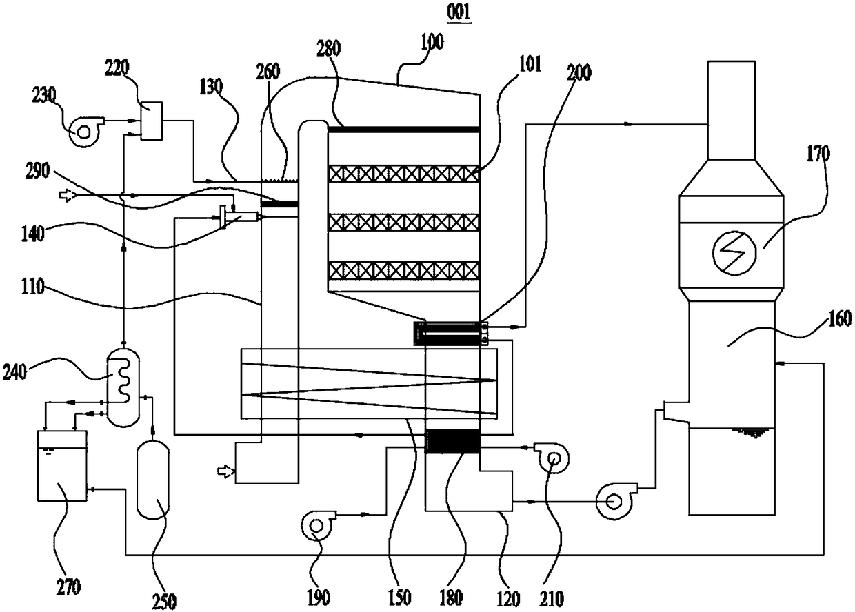
[0035] Please refer to figure 1 , figure 2 and image 3 As shown, the embodiment of the present invention provides a sintering flue gas heating denitration equipment 001, which includes a denitration tower 100 with a three-layer denitration catalyst 101 inside, and an intake flue 110 and an exhaust flue 120 connected to the denitration tower 100, The intake flue 110 is connected with an ammonia conveying pipe 130 and a flue burner 140 for heating the flue gas flowing through the intake flue 110, and the intake flue 110 and the exhaust flue 120 are connected with a Flue gas for heat exchange—flue gas reheater 150 , exhaust flue 120 is connected to desulfurization tower 160 , and wet electrostatic precipitator 170 is installed on the top of desulfurization tower 160 .

[0036] The sintering flue gas heating and denitrification equipment 001 provided by the embodiment of the present invention can effectively utilize the waste heat of the exhaust flue gas after denitrification ...

Embodiment 2

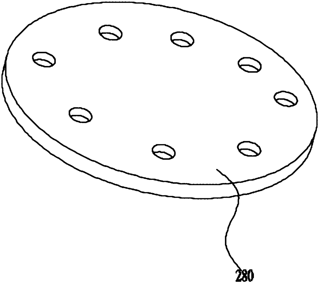
[0045] Please refer to figure 2 , image 3 and Figure 4 As shown, the embodiment of the present invention also provides a sintering flue gas heating and denitrification system, which includes the above-mentioned sintering flue gas heating and denitrification equipment 001, and the first denitration catalyst 101 is installed between adjacent denitrification catalysts 101. Three decompression plates 300, the third decompression plate 300 can reduce the flow rate of the sintering flue gas passing through the denitration catalyst 101, so that the sintering flue gas mixed with ammonia can fully contact the denitration catalyst 101 and react to remove nitrogen oxides.

[0046] The structures of the first decompression plate 280 , the second decompression plate 290 and the third decompression plate 300 are similar, only the size ratio is different.

Embodiment 3

[0048] Please refer to figure 1 , figure 2 and image 3 As shown, the embodiment of the present invention provides a sintering flue gas heating denitrification method, which is realized by using the sintering flue gas heating denitrification equipment 001 provided in the above-mentioned embodiment 1, and mainly includes the following steps:

[0049] The sintering flue gas passes through the intake flue 110 and is heated to 250-260°C by heat exchange through the flue gas-flue gas reheater 150, and heated to 300-320°C by the flue burner 140, and then mixed with the mixer 220 The mixed gas of sintering flue gas and ammonia gas is mixed and passed to the surface of the denitrification catalyst 101, and the catalytic reaction is to obtain denitrification clean flue gas;

[0050] The denitrified flue gas is sequentially cooled to 290-300°C through the secondary air preheater 200 installed on the exhaust flue 120, and then cooled to 160-170°C through the flue gas-flue gas reheater...


PUM


Abstract

The invention relates to a sintering flue gas heating denitration device and a sintering flue gas heating denitration method, which belong to the field of the treatment of industrial waste gas. The sintering flue gas heating denitration device comprises a denitration tower as well as a gas inlet flue and an exhaust flue which are connected with the denitration tower, the gas inlet flue is connected with an ammonia gas delivery pipe and a flue burner, a flue gas-flue gas reheater used for heat exchanging is connected between the gas inlet flue and the exhaust glue, the exhaust flue is connectedwith a desulphurization tower, and the top of the desulphurization tower is provided with a wet-type electric dust collector. The device effectively recycles the waste heat by adopting an energy two-level recycling method. The sintering flue gas heating denitration method comprises the following steps: heating the sintering flue gas to 300 to 320 DEG C, mixing the sintering flue gas and ammonia gas, and performing catalytic reaction to obtain denitrated pure flue gas; cooling the denitrated flue gas and the sintering flue gas before the heating in a heat exchanging manner to 150 to 160 DEG C,desulphurizing, and dedusting. By adopting the method, the waste heat is recycled by adopting the energy two-level recycling method, thereby saving the energy.

Description

technical field [0001] The invention relates to the field of industrial waste gas treatment, in particular to a sintering flue gas heating denitrification device and a sintering flue gas heating denitrification method. Background technique [0002] The sintering machine in the iron and steel plant has a large amount of smoke exhaust, which has great pollution to the environment. The main pollutant in the flue gas discharged from the sintering machine is NO X , SO 2 and dust. Therefore, the flue gas of the sintering plant must be treated with flue gas desulfurization and denitrification to reduce pollution. [0003] Due to the low temperature of sintering flue gas, wet desulfurization is generally used in domestic sintering machines at present, and no denitrification device is installed, and white smoke is easy to appear at the chimney outlet. According to environmental protection requirements, most domestic sintering plants need to carry out denitrification modification. ...

Claims


Application Information

Patent Timeline
IPC IPC(8): B01D53/86B01D53/50B01D47/00B01D53/56F23L15/04F27D17/00
CPCB01D47/00B01D53/507B01D53/8625F23L15/04F27D17/004F27D17/008B01D2251/2062B01D2258/0283Y02E20/34Y02P10/25
Inventor 张兵徐超周冲陶惠祥秦峰潘春锋姜静夏小群刘升
Owner CHINA CITY ENVIRONMENT PROTECTION ENGINEERING LIMITED COMPANY
Learn More