
Metal film laminate structure

一种金属膜、构造的技术,应用在金属层状产品、金属材料涂层工艺、金属花纹材料等方向,能够解决底涂层表面凹凸变大、难金属纳米粒子群排列底涂层、无法得到密合力均匀电路等问题,达到简便层积构造的效果

Active Publication Date: 2018-07-17
EEJA LTD
View PDF11 Cites 5 Cited by
  • Summary
  • Abstract
  • Description
  • Claims
  • Application Information

AI Technical Summary

Problems solved by technology

Therefore, the conventional method has the disadvantage that in order to exert an anchoring effect between the insulating base material and the plated precipitation layer, the unevenness of the surface of the primer layer becomes large, etc., and the surface shape of the primer material used is different. limited
However, even when the pretreatment liquid is applied to a general insulating substrate to form a catalyst nucleus, the deposited metal film formed by electroless plating or subsequent electroplating may have insufficient adhesion to the substrate.
[0015] For example, the following problems occur: In the case of large-area plating, there are places where the adhesion of the metal film is weak
[0017] However, in reality, it is difficult to planarly arrange metal nanoparticles with uniform particle size on the undercoat layer.

Method used


Image

  • Metal film laminate structure
  • Metal film laminate structure
  • Metal film laminate structure

Examples


Embodiment 1

[0066] As the insulating base material A, glass (EAGLE XG manufactured by CORNING) was used. A polyester resin solution (glass transition temperature (measured value) 72°C) was used as the primer solution. The primer solution was applied to the insulating substrate A by a bar coating method and dried at 100°C for 5 minutes to form an undercoat layer having a thickness of 0.12 μm in terms of a dry film thickness.

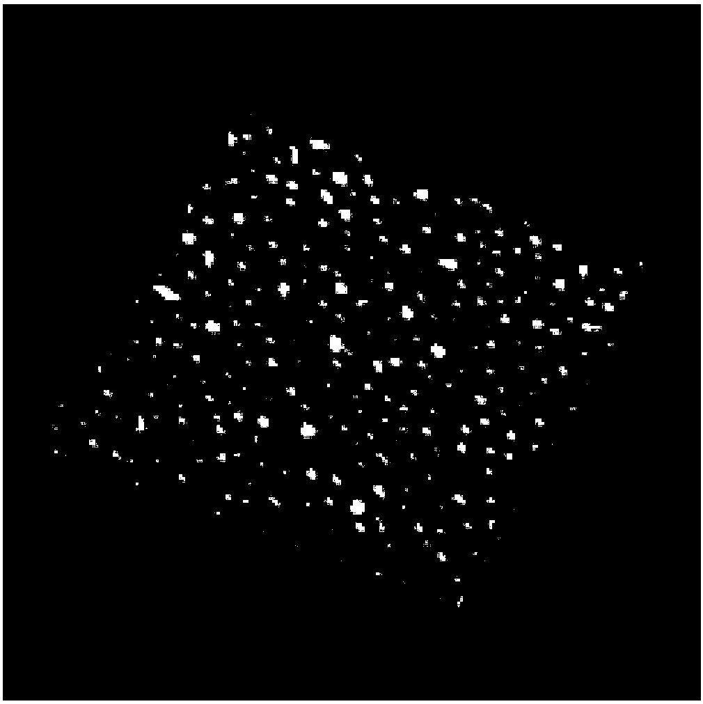
[0067] The insulating substrate A provided with the primer layer is immersed in colloidal spherical gold (Au) nanoparticles (0.1g / L as Au) containing an average particle diameter of 20nm (variation coefficient CV=0.15) After 10 minutes in the aqueous solution of ), wash with pure water. As a result, nanoparticles with an average particle diameter of 20 nm were obtained with an average adsorption density of 273 particles / 0.25 μm 2 The substrate of the catalyst layer adsorbed on the primer layer ( image 3 ). The surface shape was observed using a scanning probe microsc...

Embodiment 2

[0074] As the insulating base material B, a polyester film (Lumirror S10 manufactured by Toray Co., Ltd.) was used. As the primer solution, a polyester resin solution containing an amine group (glass transition temperature 80°C) was used. The primer solution was applied on the insulating substrate B by a bar coating method and dried at 100° C. for 5 minutes to form an undercoat layer with a thickness of 0.07 μm in terms of a dry film thickness.

[0075] Next, the substrate was irradiated with light of a wavelength of 300 nm or less from a distance of 10 mm with an ultraviolet lamp light source device (Model 312 manufactured by Technovision, Inc.) for 30 seconds. Between the light source and the substrate, a quartz mask with a shading pattern formed of chromium is placed. As a result, the amine group on the primer irradiated with ultraviolet rays disappears.

[0076] The insulating substrate B treated in this way is immersed in colloidal spherical gold (Au) nanoparticles (0.1g / L a...

Embodiment 3

[0080] As the insulating substrate C, a polyimide film (UPILEX 50SGA manufactured by Ube Industries Co., Ltd.) was used. The primer solution was an olefin resin solution (glass transition temperature 130°C). The primer solution was applied on the insulating substrate B by a spin coating method and dried at 150° C. for 15 minutes to form a primer layer having a thickness of 0.3 μm in terms of dry film thickness.

[0081] The insulating substrate C provided with the primer layer is immersed in spherical palladium (Pd) nanoparticles (0.3g / L as Pd) dispersed in a colloidal shape with an average particle diameter of 3nm (variation coefficient CV=0.40) ) And polyethyleneimine (average molecular weight 10,000) 0.01 g / L in an aqueous solution for 10 minutes to obtain a substrate on which a palladium (Pd) nanoparticle catalyst layer adsorbed on the primer layer was formed.

[0082] Next, the substrate was immersed in an electroless palladium (Pd) plating solution (LECTROLESS Pd2000S manufa...


PUM

PropertyMeasurementUnit
glass transition temperatureaaaaaaaaaa
particle diameteraaaaaaaaaa
glass transition temperatureaaaaaaaaaa

Abstract

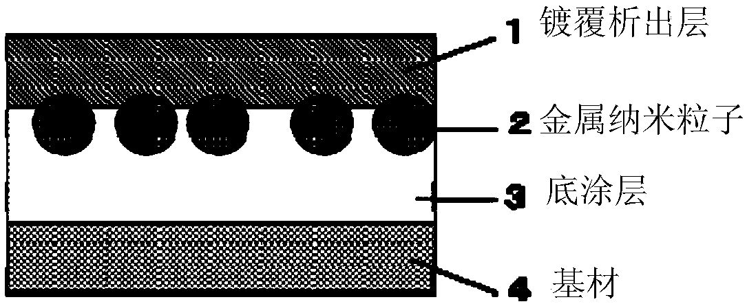
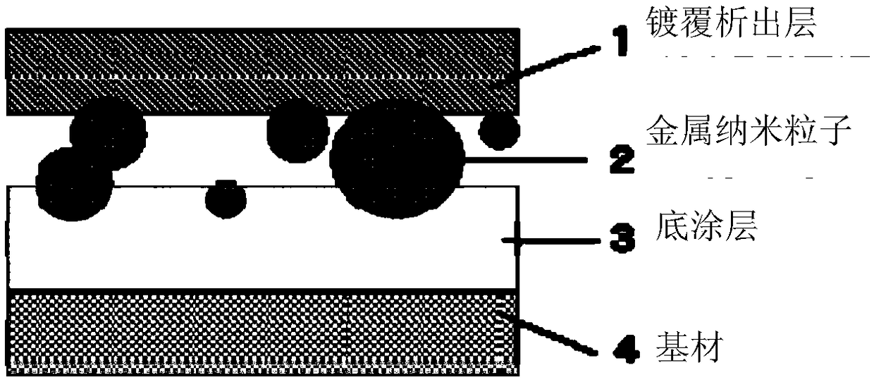
The present invention addresses the problem of the inability to form a uniform metal film due to weak adhesion of a deposition metal film making it impossible to obtain a uniform adhesive force, or due to partial aggregation of metal nanoparticles resulting in a decrease in the adsorption force of some of the metal nanoparticles with respect to a primer layer, and provides a metal film laminate structure in which metal nanoparticles of a catalyst layer are surrounded by a primer layer of which one end is bonded to a plating deposition layer. The metal film laminate structure of the present invention has a cross sectional structure in which three layers, namely a primer layer, a catalyst layer, and a plating deposition layer, are laminated on a base material, characterized in that the primer layer is a resin layer with a glass transition temperature (Tg) of 40 to 430DEG C, and the catalyst layer comprises a group of metal nanoparticles arranged in a planar fashion on the primer layer, wherein the group of metal nanoparticles comprises a metal of group IB or group VIIIB in the periodic table, and wherein the metal nanoparticles are surrounded by the primer layer, of which one end isbonded to the plating deposition layer.

Description

Technical field [0001] The present invention relates to a laminated structure of a metal film having good adhesion to a base material, and particularly to a laminated structure having good adhesion to an insulating base material. Background technique [0002] In the past, electroless plating has been widely used in industry as a base metal or base metal alloy such as nickel (Ni), copper (Cu), cobalt (Co), or silver (Ag), gold (Au) directly formed on the surface of an insulating substrate. , Platinum (Pt), palladium (Pd) and other precious metals or precious metal alloy metal film method. [0003] Among the insulating substrates subjected to electroless plating, there are various compositions such as glass, inorganic oxides, inorganic compounds, plastics, ceramics, organic compounds, cellulose, cloth, rubber, or composites of these. [0004] Among the specific inorganic compound-based insulating substrates, there are glass, alumina, ZnO, Cu 2 Inorganic oxides such as O; inorganic com...

Claims


Application Information

Patent Timeline
Patent Type & Authority Applications(China)
IPC IPC(8): C23C28/00B32B15/01B32B15/08C23C18/42C25D5/54C25D7/00H05K3/18
CPCH05K2201/0145H05K2201/0158H05K2201/0257B32B15/16C23C30/00C23C18/2033C23C18/1865C23C18/1608C23C18/1612C23C18/1653C23C18/1868C23C18/1893C23C18/204C23C18/2086C23C18/30H05K3/387C23C18/42H05K1/032H05K2203/0709H05K2203/1105C23C18/1639C23C18/1641C23C18/1844C23C18/1882C23C28/00H05K3/181H05K3/185B32B15/01B32B15/08H05K2203/072H05K1/09
Inventor 伊东正浩
Owner EEJA LTD
Learn More