Tail gas treatment method of biomass incinerator

A technology for tail gas treatment and biomass, which is applied in gas treatment, separation methods, chemical instruments and methods, etc., can solve the problems of insufficiency, outdated and backward processes, consumption of ammonia water, etc., to reduce operation and maintenance costs, simple process methods, The effect of reducing process material consumption

Inactive Publication Date: 2018-08-10
YANSHAN UNIV
View PDF7 Cites 5 Cited by
  • Summary
  • Abstract
  • Description
  • Claims
  • Application Information

AI Technical Summary

Problems solved by technology

Although the United States has completed a 90-day test with four people using the above-mentioned tail gas treatment process, the process has the following shortcomings: 1) The cyclone dust collector increases the overall power consumption and maintenance costs of the system, 2) Catalytic reduction consumes ammonia water, which increases the burden of material supplies. 3) The high operating temperature of the catalyst results in high power consumption to maintain the normal operation of the system
[0004] In the published patents or documents, the treatment...

Method used


Image

  • Tail gas treatment method of biomass incinerator

Examples


Embodiment 1

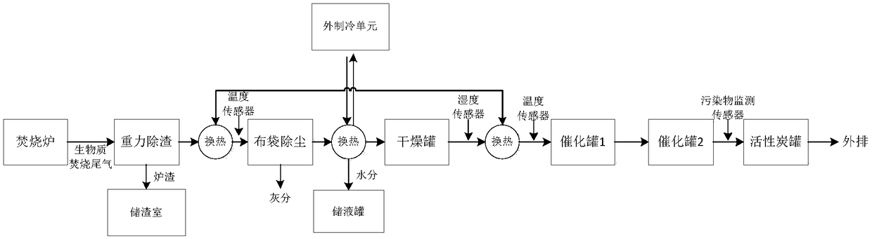
[0019] Such as figure 1 As shown, the present invention comprises four process steps of dust removal, water removal, catalytic reduction and catalytic oxidation:

[0020] (1) Dust removal: The biomass incineration exhaust gas produced by the incinerator first passes through the high temperature zone to melt the ash, and then condenses into blocks through the low temperature zone. The temperature is lowered to 130°C, and a temperature sensor is installed on the heat exchanger. Finally, the dust with a particle diameter greater than 2.5 μm is removed by a ceramic filter and a bag filter, and a pressure sensor is installed at the rear end of the bag filter;

[0021] (2) Water removal: The tail gas after dust removal is directly passed into the heat exchanger, and the temperature of the heat exchanger is 9°C±1°C, so that the water vapor in the tail gas will condense, and the liquid water will flow into the liquid storage tank along the guide tube, a small amount The uncondensed w...

Embodiment 2

[0025] (1) Dust removal: The biomass incineration exhaust gas produced by the incinerator first passes through the high temperature zone to melt the ash, and then condenses into blocks through the low temperature zone. The temperature is lowered to 150°C, and a temperature sensor is installed on the heat exchanger. Finally, the dust with a particle diameter greater than 2.5 μm is removed by using a ceramic filter and a bag filter;

[0026] (2) Water removal: The tail gas after dust removal is directly passed into the heat exchanger, and the temperature of the heat exchanger is 9°C±1°C, so that the water vapor in the tail gas is condensed, and the liquid water flows into the liquid storage tank along the draft tube. A small amount of uncondensed water vapor is further dried through a drying tank filled with water-absorbing silica gel to completely remove the moisture in the exhaust gas. A humidity sensor is installed behind the drying tank;

[0027] (3) Catalytic reduction: the...

Embodiment 3

[0030] (1) Dust removal: The biomass incineration exhaust gas produced by the incinerator first passes through the high temperature zone to melt the ash, and then condenses into blocks through the low temperature zone. The temperature is lowered to 170°C, and a temperature sensor is installed on the heat exchanger. Finally, the dust with a particle diameter greater than 2.5 μm is removed by using a ceramic filter and a bag filter;

[0031] (2) Water removal: The tail gas after dust removal is directly passed into the heat exchanger, and the temperature of the heat exchanger is 9°C±1°C, so that the water vapor in the tail gas is condensed, and the liquid water flows into the liquid storage tank along the guide pipe. A small amount of uncondensed water vapor is further dried through a drying tank filled with water-absorbing silica gel to completely remove the moisture in the exhaust gas. A humidity sensor is installed behind the drying tank;

[0032] (3) Catalytic reduction: the...


PUM

PropertyMeasurementUnit
Diameteraaaaaaaaaa

Abstract

The invention provides a biomass incineration tail gas treatment method. The biomass incineration tail gas treatment method mainly comprises the following steps: enabling biomass incineration tail gasto pass through a high-temperature region and melting ash residues; then enabling the biomass incineration tail gas to pass through a low-temperature region and condensing into a block; then carryingout gravitational sedimentation to remove large-particle ash residues; then carrying out heat exchange and cooling the temperature of the tail gas to 130 to 170 DEG C; then removing dust through a ceramic filter and a cloth bag to remove micron dust; treating the tail gas through a heat exchanger and reducing the temperature, so as to condense water steam into liquid-state water; then recycling the liquid-state water into a liquid storage tank; after drying residual water steam through a drying tank, raising the temperature of the tail has to 110 to 140 DEG C through heat exchange of a hearthand directly introducing the tail gas into a catalysis tank 1; taking carbon monoxide in the tail gas as a reducing agent and removing nitrogen oxide; then enabling the tail gas to pass through a catalysis tank 2; removing the residual carbon monoxide and volatile organic pollutants by utilizing excessive oxygen in the tail gas; after an instrument monitors that the tail gas is qualified, discharging the tail gas through an activated carbon security tank. The biomass incineration tail gas treatment method provided by the invention has the advantages of simple and feasible procedure and relatively low energy consumption and material consumption; the biomass incineration tail gas treatment method is especially suitable for biomass incineration tail gas treatment in a controlled ecological life-support system.

Description

technical field [0001] The invention belongs to the technical field of waste treatment, in particular to a tail gas treatment method of a space biomass incinerator. Background technique [0002] With the development of space exploration technology, future manned deep space exploration missions and alien planet migration become possible. In order to ensure that human beings can survive in a small and confined space, it is necessary to establish an artificial ecological cycle system, that is, a bio-regenerative life support system. Among them, the incinerator is one of the necessary means to return material elements such as carbon, hydrogen, oxygen, and inorganic salts to the material flow cycle through high-temperature oxidation of solid waste such as inedible biomass. However, the biomass incineration flue gas contains ash, ash, water vapor, NO x , CO and VOCs, the composition is very complex. In order to directly discharge the flue gas to each cabin, various pollutant in...

Claims


Application Information

Patent Timeline
IPC IPC(8): B01D50/00B01D53/86B01D53/62B01D53/56B01D53/44
CPCB01D53/261B01D53/8625B01D53/864B01D53/8687B01D2255/20707B01D2255/20723B01D2255/1021B01D2255/1023B01D2255/204B01D2253/106B01D2255/2092B01D2251/102B01D2251/204B01D2257/708B01D2257/502B01D50/20Y02A50/20
Inventor 王洪超王风彦田冀锋徐朝鹏王海燕
Owner YANSHAN UNIV
Why Eureka
Try Eureka