
Thermodynamic method and system for cement kiln to realize cooperative treatment of domestic garbage

A technology for domestic waste and co-processing, applied in cement production, combustion methods, waste heat treatment, etc., can solve the problems of high transportation cost, heat loss, energy waste, etc., and achieve economic benefits, increase power generation, and improve economic efficiency. Effect

Inactive Publication Date: 2018-09-07
新弘源科技股份有限公司
View PDF1 Cites 2 Cited by
  • Summary
  • Abstract
  • Description
  • Claims
  • Application Information

AI Technical Summary

Problems solved by technology

[0003] The existing cement kiln synergistic treatment methods have the following problems: 1. Excessive utilization of waste heat in the cement production process, resulting in loss and waste of heat energy; 2. Initial air temperature of the primary and secondary air of the incineration boiler is low, resulting in energy waste Moreover, the primary and secondary air humidity is high, which seriously corrodes the air preheater and superheater; 3. The slag reduction rate of the grate furnace is difficult to reach the standard 5%, which affects the quality of cement as a cement raw material; 4. The grate furnace smoke The gas directly enters the cement kiln decomposition furnace, causing excessive NOx emissions in the subsequent flue gas treatment; 5. The layout of the cement plant is scattered and far away from the urban area, and the domestic waste is co-processed, and the transportation cost is high

Method used


Image

  • Thermodynamic method and system for cement kiln to realize cooperative treatment of domestic garbage
  • Thermodynamic method and system for cement kiln to realize cooperative treatment of domestic garbage
  • Thermodynamic method and system for cement kiln to realize cooperative treatment of domestic garbage

Examples


Embodiment 1

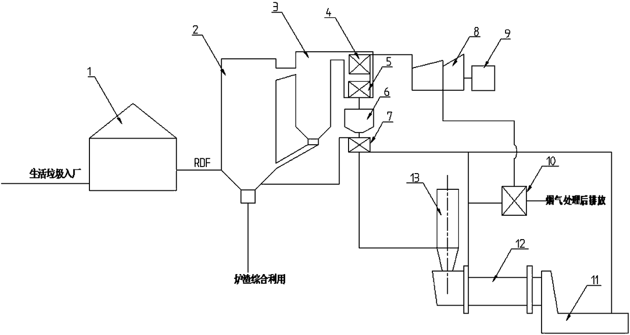
[0039] Such as figure 1 As shown, a thermal system for coordinating domestic waste in a cement kiln according to the present invention includes a waste incineration system, a power generation system, a cement production system and other auxiliary systems. The waste incineration system includes sequentially connected RDF production plants 1, fluidized bed incinerator 2, cyclone separator 3, superheater 4 and economizer 5, the power generation system includes an intake steam turbine 8 and a generator 9, the superheater is connected with the intake steam turbine and generator in turn, and other auxiliary systems include The denitrification device connected to the fluidized bed incinerator, the air preheater 7 connected to the cement calcining rotary kiln, and the waste heat boiler 10 for collecting the waste heat of the cement rotary kiln. The cement production system includes a cement decomposition furnace 13, a cement calcining rotary kiln 12 and a cement cooking The material c...

Embodiment 2

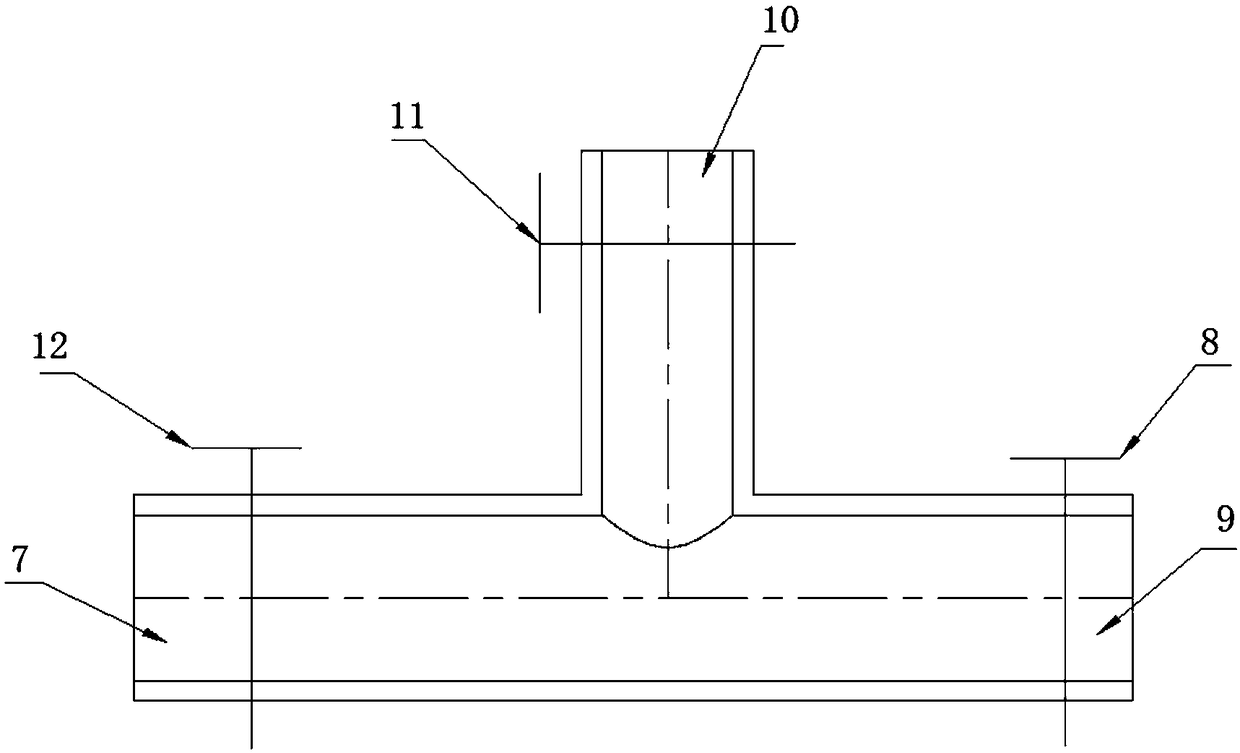
[0041] Such as image 3 As shown, the air supply pipe of the air preheater is a three-prong pipe structure, which are the flue gas inlet pipe of the cement calcining rotary kiln, the cooling air inlet pipe and the mixing pipe of the cement clinker cooling section. The flue gas inlet pipe of the cement calcining rotary kiln, the cooling air inlet pipe and the mixing pipe of the cement clinker cooling section are respectively provided with flue gas valves. All the other technical features are the same as in Embodiment 1.

[0042]The cooling air in the cement clinker cooling section is used as a high-temperature gas due to the high temperature of the cement clinker, and is used as the primary air of the fluidized bed incinerator, which has the effect of increasing the temperature of the furnace and improving the heat utilization efficiency.

[0043] All the other technical features are the same as in Embodiment 1.

Embodiment 3

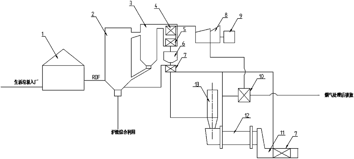
[0045] Such as figure 2 As shown, the air preheater is segmented, divided into air preheater section I14 and air preheater section II15, air preheater section I is connected to the tail flue of the fluidized bed incinerator, and the air preheater Section II is arranged in the cement clinker cooling section. The air supply pipe of the air preheater section I is a trident pipe structure, which are respectively the flue gas inlet pipe of the cement calcining rotary kiln, the heat exchange air inlet pipe and the mixing pipe of the air preheater section II, and the three pipes are respectively equipped with flue gas Air intake pipe control valve, heat exchange air intake pipe control valve and mixing pipe control valve. According to the fuel situation of the waste incinerator, the intake ratio and intake volume can be controlled in real time, so as to control the primary air volume and achieve the purpose of stable and efficient combustion.

[0046] All the other technical featu...


PUM


Abstract

The invention relates to a thermodynamic method and a thermodynamic system for a cement kiln to realize cooperative treatment of domestic garbage and belongs to the technical field of garbage treatment. The thermodynamic method for the cement kiln to realize cooperative treatment of domestic garbage comprises the following steps of: (1) conveying the domestic garbage to an RDF manufacturing plant;(2) conveying RDF to a fluidized bed incinerator, wherein high-temperature flue gas generated in incineration enters a cyclone separator, passes through an over-heater, a coal economizer, a denitrating device and an air preheater after recycling a part of a fuel and then enters a decomposition furnace and a cement burning rotary kiln; and high-temperature steam generated by the over-heater entersa steam replenishing type steam turbine and is used for driving a generator to generate electricity; and (3) conveying furnace slags generated by garbage incineration to a cement kiln raw material storehouse and obtaining cement clinkers after cement burning and rotary kiln burning. The invention further provides the thermodynamic system for the cement kiln to realize cooperative treatment of thedomestic garbage; a cement production system and a garbage incineration system share one set of flue gas treatment equipment, so the investment is lowered, the cost is lowered, and the economical efficiency of the whole plant is improved.

Description

technical field [0001] The invention relates to a thermal method and a system for coordinating domestic garbage in a cement kiln, and belongs to the technical field of garbage treatment. Background technique [0002] The principle of using cement kilns to co-process municipal solid waste is similar to that of incineration power generation, which uses high temperature to process waste. Since the cement kiln temperature is higher than that of the waste incineration plant, on the one hand, the cement burning system can be used to digest the odor and toxic substances in the waste treatment process; Toxic substances can be decomposed into corresponding inorganic substances and heavy metals and solidified in cement clinker. The co-processing of solid waste in cement kilns is of great significance to both solid waste treatment and the development of the cement industry. [0003] The existing cement kiln synergistic treatment methods have the following problems: 1. Excessive utili...

Claims


Application Information

Patent Timeline
IPC IPC(8): F23G5/44F23G5/46F23J15/02F27D17/00
CPCF23G5/44F23G5/46F23J15/022F27D17/004Y02P10/25Y02P40/121
Inventor 张德昌戴宇晴
Owner 新弘源科技股份有限公司
Features
  • Generate Ideas
  • Intellectual Property
  • Life Sciences
  • Materials
  • Tech Scout
  • Unparalleled Data Quality
  • Higher Quality Content
  • 60% Fewer Hallucinations
Learn More