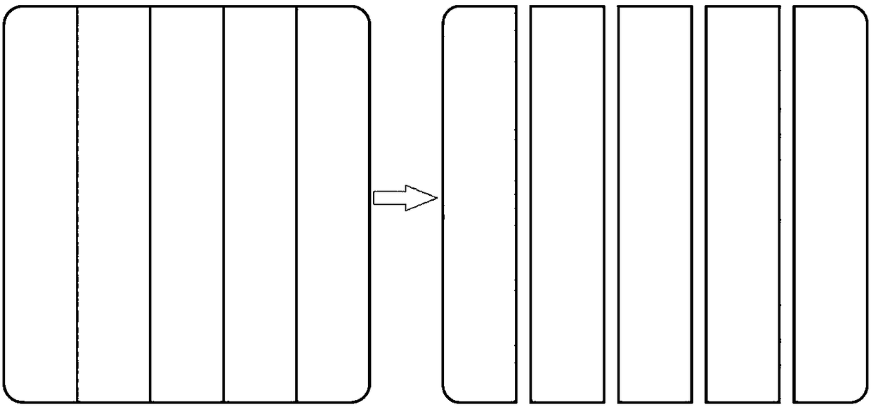
Solar cell grid line structure, solar cell sheet and solar laminate module

A technology for solar cells and solar cells, applied in the field of solar cells, can solve the problems of high battery cost, overflowing glue, increase the consumption of silver paste and battery cost, etc., and achieve the effect of avoiding glue overflowing and glue leakage and good electrical conductivity.

Pending Publication Date: 2018-09-14
LONGI SOLAR TECH (TAIZHOU) CO LTD
View PDF7 Cites 8 Cited by
  • Summary
  • Abstract
  • Description
  • Claims
  • Application Information

AI Technical Summary

Problems solved by technology

(1) The consumption of silver paste is more, resulting in higher battery cost
(2) For some types of conductive adhesives, there is a risk of overflow or seepage
But this will further increase the consumption of silver paste and battery cost

Method used


Image

  • Solar cell grid line structure, solar cell sheet and solar laminate module
  • Solar cell grid line structure, solar cell sheet and solar laminate module
  • Solar cell grid line structure, solar cell sheet and solar laminate module

Examples


Embodiment Construction

[0060] The technology of the present invention is described in detail below in conjunction with accompanying drawing:

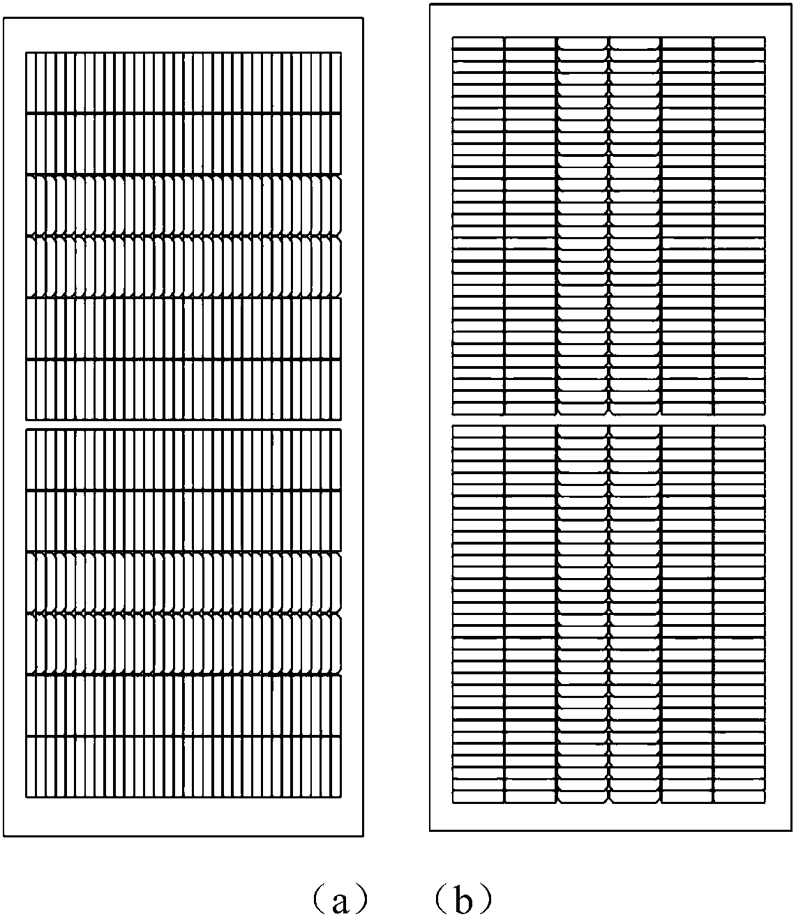
[0061] The battery metallization pattern scheme of the present invention is as follows Figure 8 As shown, it includes main grid lines 2 in the form of a cross grid, and auxiliary grid lines 1 . The busbar 2 is a network structure composed of interlaced thin lines 7, and the thin lines 7 are one or more combinations of straight lines, broken lines and curves; grooves are formed in the grid of the network structure, and the busbar 2 When the conductive glue 6 is applied, part of the conductive glue 6 is filled in the grooves of the grid.

[0062] Such as Figure 8 As shown in (b), the thin lines 7 of the bus bars 2 may be composed of straight lines, broken lines or curved lines. The width of the thin line 7 ranges from 5 microns to 1500 microns, the height of the thin line 7 ranges from 5 microns to 100 microns, the characteristic length of the grid holes r...


PUM


Abstract

The invention provides a solar cell grid line structure, a solar cell sheet and a solar lamination module. The grid line structure comprises a plurality of sub grid lines arranged on a silicon wafer and a main grid line perpendicular to the sub grid lines. The main grid line is formed by a grid-like porous structure. When the main grid line is coated with a conductive paste, grid holes are filledwith a part of the conductive paste. Since the materials of the conductive paste and the main grid line have good electrical conductivity, when the above grid lines are sufficiently dense, the use ofa grid pattern instead of a solid pattern does not seriously affect the electrical performance of a module. The deformation of the conductive paste and the diffusion on a cell shell texture covered bysilicon nitride are limited by the grid pattern of the main grid line and are limited in the grid pattern, and thus paste overflow and bleeding are avoided.

Description

technical field [0001] The invention belongs to the field of solar cells, and in particular relates to a solar cell grid structure, a solar cell and a solar stack assembly. Background technique [0002] A solar cell is a device that uses the photovoltaic effect to directly convert light energy into direct current. According to different photoelectric conversion materials, solar cells include monocrystalline silicon, polycrystalline silicon, amorphous silicon thin films, cadmium telluride thin films, copper indium gallium tin thin films, gallium arsenide, fuel sensitization, perovskite, stacked layers, etc. . The most common of these are crystalline silicon solar cells, including monocrystalline silicon solar cells and polycrystalline silicon solar cells. Solar cells are usually in the shape of a sheet. The side that absorbs light energy and converts it into electricity is called the light-absorbing side or front side, and the other side is called the back side. For some s...

Claims


Application Information

Patent Timeline
Patent Type & Authority Applications(China)
IPC IPC(8): H01L31/05H01L31/04
CPCH01L31/043H01L31/0508Y02E10/50
Inventor 郑直胡栋苗劲飞焦方凯
Owner LONGI SOLAR TECH (TAIZHOU) CO LTD
Why Eureka
Try Eureka