

Luminescent probe and time resolution fluorescence detection system
A time-resolved fluorescent and luminescent probe technology, applied in the field of luminescent probes, can solve the problems of weak fluorescence intensity, poor biocompatibility, and low energy conversion efficiency of materials, and achieve good biocompatibility, high energy conversion efficiency, The effect of high signal-to-noise ratio
- Summary
- Abstract
- Description
- Claims
- Application Information
AI Technical Summary
Problems solved by technology
Method used
Image

Examples
Embodiment 1
[0050] Example 1 Luminescence probe NaYbF 4 @CaF 2 Preparation of nanoparticles (@ represents the wrapping of the shell, the same below)
[0051] Take 10mmol oleic acid (2.82g), 10mmol oleylamine (2.67g), 20mmol octadecene (5.04g), 1mmol ytterbium trifluoroacetate, 1mmol sodium trifluoroacetate (136mg), put into a 100mL three-necked flask and stir, The system was sealed, the temperature was raised to 110° C. and vacuumed for 30 minutes, nitrogen protection was introduced, and the temperature was raised to 300° C. for 30 minutes to react. Cool naturally after the reaction, add 30 mL of absolute ethanol to the system, centrifuge at 15,000 rpm for 8 min, collect the precipitate, and disperse it in cyclohexane.
[0052] Take 20mmol oleic acid (5.64g), 20mmol octadecene (5.04g), 1mmol NaYbF dispersed in cyclohexane 4 Nucleus, 4 mmol of calcium trifluoroacetate, under the condition of nitrogen protection, the temperature was raised to 110°C to remove cyclohexane and water, then vac...
Embodiment 2
[0054] Example 2 Luminescent Probe NaYbF 4 @NaYF 4 Preparation of nanoparticles
[0055] 1 mmol YbCl 3 Mix with oleic acid and octadecene, heat up to 110°C to form a clear solution, after cooling down to room temperature, add NaOH and NH 4 The methanol solution of F was heated up to 110°C to remove methanol and water, protected by nitrogen gas, then heated up to 300°C, and kept at a constant temperature for 45 minutes. After cooling to room temperature, add 30 mL of ethanol, centrifuge at 15,000 rpm / min for 8 min, collect the precipitate, and disperse it in cyclohexane.
[0056] 1 mmol YbCl 3 Mix with oleic acid and octadecene, heat up to 110°C to form a clear solution, after cooling down to room temperature, add NaOH and NH 4 Methanol solution of F, then add 1 mmol of synthesized NaYbF 4 Then raise the temperature to 110°C to remove methanol and water, pass nitrogen protection, then raise the temperature to 300°C, and keep the temperature constant for 45min. After cool...
Embodiment 3
[0058] Example 3 Determination of Luminescent Probe NaYbF Using a Laser-Pumped Time-Resolved Detection System 4 @CaF 2 and NaYbF 4 @NaLuF 4 The time-resolved spectrum of
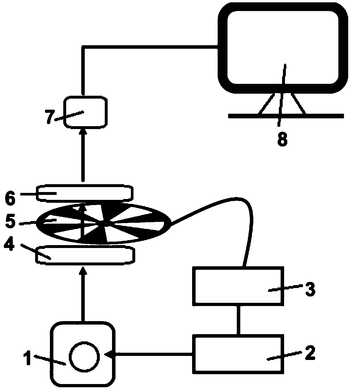
[0059] Place the dispersion made of nanomaterials in the cuvette, place the cuvette on the sample stage, turn on the arbitrary waveform generator and the semiconductor laser, aim the pulsed excitation light at the sample cell, and the generated fluorescence signal passes through the converging lens Group, optical chopper, beam expander lens group and detection fiber, and finally enter the fiber optic spectrometer (NOVA-EX, Fuxiang Optics), and collect and process the spectrum by computer.
[0060] Figure 4 It is the fluorescence spectrum diagram of the luminescence probe in this embodiment, and the collection range is 400-1100 nanometers; wherein, (a) is the fluorescence spectrum diagram of the luminescence probe NaYbF4@CaF2, and (b) is the fluorescence spectrum of the luminescence probe NaYbF4@NaYF4 S...
PUM
| Property | Measurement | Unit |
|---|---|---|
| Particle size | aaaaa | aaaaa |
| Concentration | aaaaa | aaaaa |
| Particle size | aaaaa | aaaaa |
Abstract
Description
Claims
Application Information