
Amorphous Ga2O3 solar-blind ultraviolet detector and preparation method and application thereof

An ultraviolet detector and detector technology, applied in semiconductor devices, final product manufacturing, sustainable manufacturing/processing, etc., can solve the problems of optical band gap change, poor structural repeatability, high cost, and achieve improved response speed, excellent Stable, stable performance

Active Publication Date: 2018-12-07
INST OF PHYSICS - CHINESE ACAD OF SCI
View PDF1 Cites 23 Cited by
  • Summary
  • Abstract
  • Description
  • Claims
  • Application Information

AI Technical Summary

Problems solved by technology

[0004] Existing about Ga 2 o 3 In the reports of solar-blind photodetectors, some are based on nanostructures and some are based on thin films. However, the preparation and synthesis process of nanomaterials is not easy for most researchers to master, and the purity of the source materials is not easy to improve, and the structure repeatability is poor. , so the film type still dominates
In the prior art, in order to obtain high crystalline quality Ga 2 o 3 Thin films, the vast majority of researchers use single crystal substrates and high-temperature complex growth processes, such as molecular beam epitaxy, pulsed laser deposition and metal-organic chemical vapor deposition techniques, etc. The required high-temperature and high-vacuum conditions are expensive, which is not conducive to large-scale industrial applications, and it is impossible to realize the application of flexible solar-blind ultraviolet detection; Good suppression results in the capture and gradual release of photogenerated carriers, causing the device to produce a serious persistent photoconductivity (PPC) phenomenon, which is far from the key element of fast response speed in the basic requirements of the detector.
Although in existing reports, there are researches about changing the deposition temperature to control oxygen vacancies in amorphous gallium oxide (see OxygenDeficiency and Sn Doping of Amorphous Ga 2 o 3 [J]. Applied Physics Letters, 2016, 108, 022107.), but the amorphous gallium oxide film prepared at a moderate temperature (320-425°C) seriously deviates from the stoichiometric ratio, so that the optical band gap occurs relatively Large change (4~4.5eV), unable to meet the response of the sun-blind band
[0005] Combining the two main shortcomings of the above-mentioned high-temperature growth process and the serious PPC phenomenon in the prior art, it is urgent to develop a Ga 2 o 3 Solar-blind photodetector and preparation method thereof

Method used


Image

  • Amorphous Ga2O3 solar-blind ultraviolet detector and preparation method and application thereof
  • Amorphous Ga2O3 solar-blind ultraviolet detector and preparation method and application thereof
  • Amorphous Ga2O3 solar-blind ultraviolet detector and preparation method and application thereof

Examples


Embodiment 1

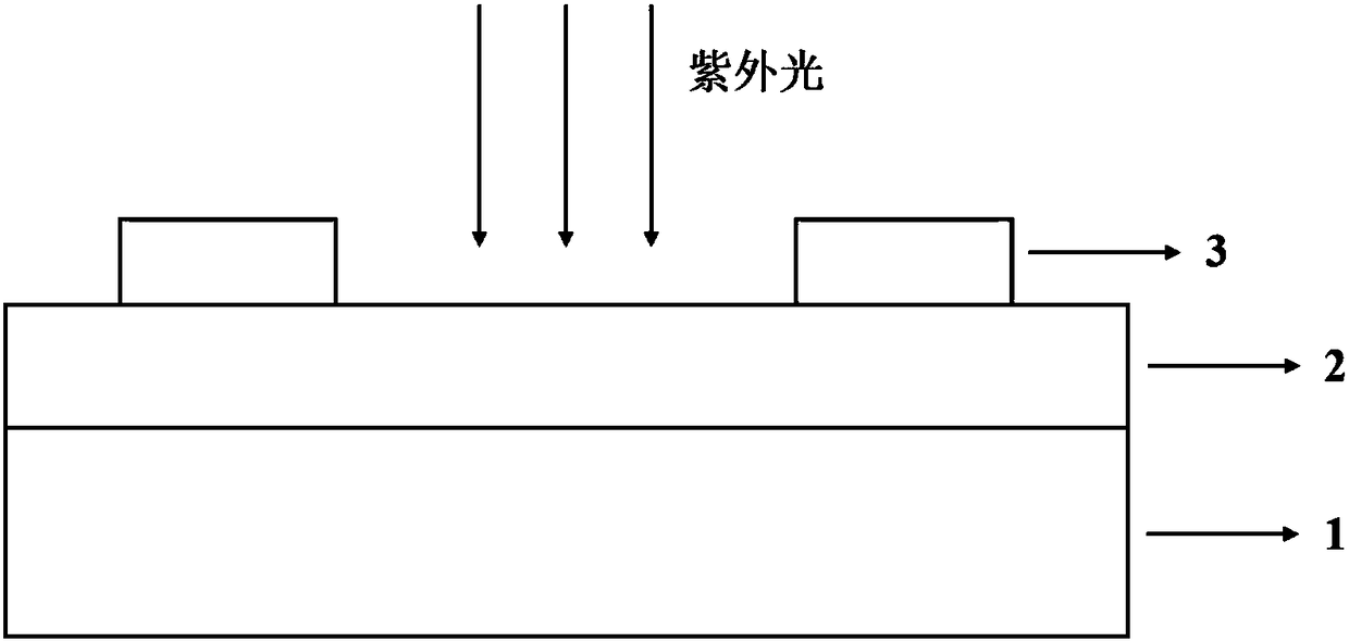
[0039] This embodiment is used to illustrate the amorphous Ga of the present invention 2 o 3 Fabrication process of solar-blind UV detector. figure 1 The amorphous Ga of this embodiment 2 o 3 Schematic diagram of the structure of a solar-blind ultraviolet detector. Such as figure 1 As shown, the detector includes a deep ultraviolet ultrapure quartz substrate 1 , a gallium oxide thin film active layer 2 and an indium tin oxide interdigitated electrode 3 from bottom to top.

[0040] The specific preparation method of the sun-blind ultraviolet detector of the present embodiment is as follows:

[0041] 1) A 25mm×25mm×0.5mm far-ultraviolet ultrapure quartz substrate was ultrasonically cleaned, dried with dry high-purity nitrogen, and placed on a sample holder of the same size. After fixing the substrate, put it into the magnetron sputtering chamber equipped with a gallium oxide ceramic target (purity: 99.999%), raise the sample stage to the highest point (the distance between...

Embodiment 2

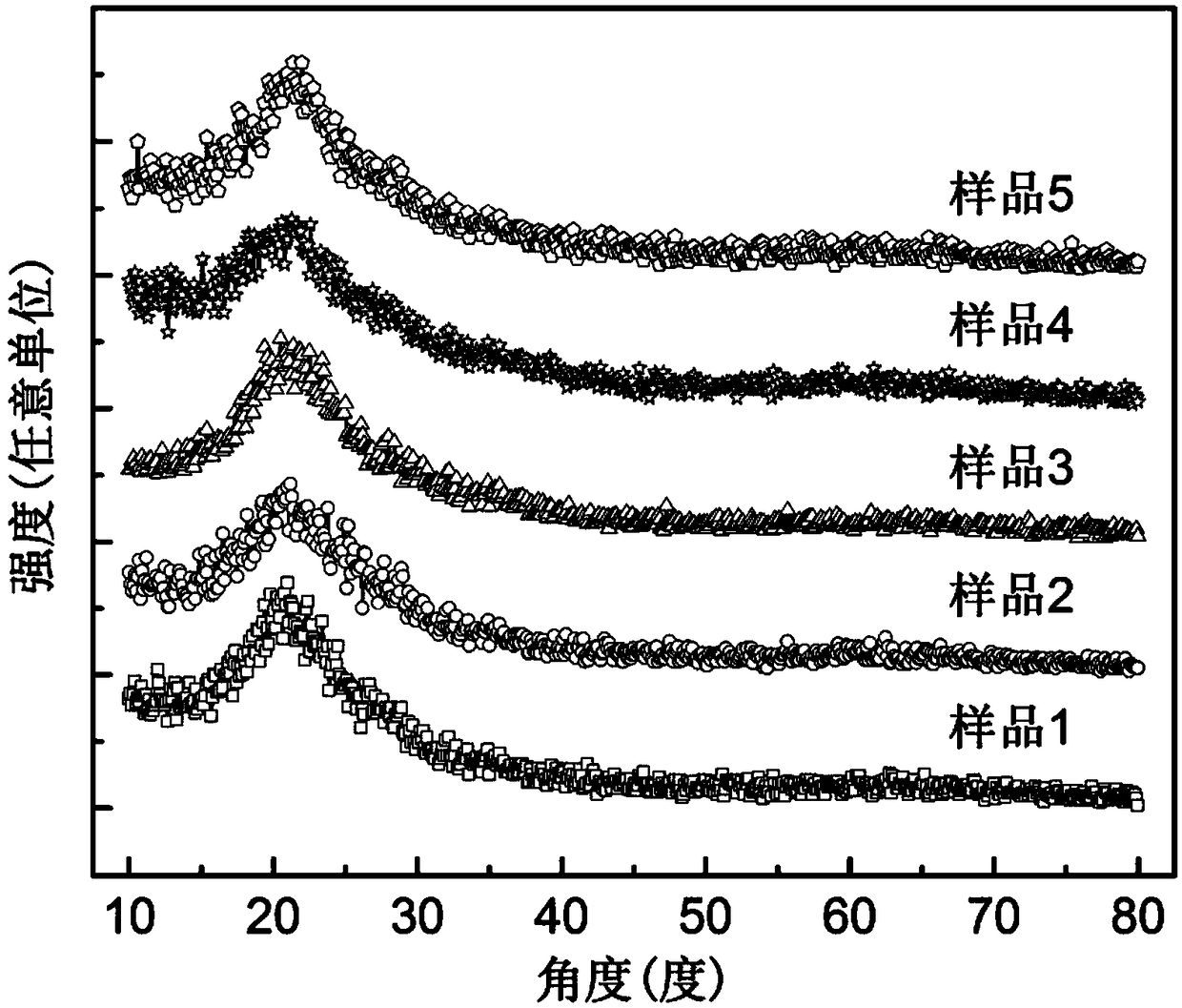
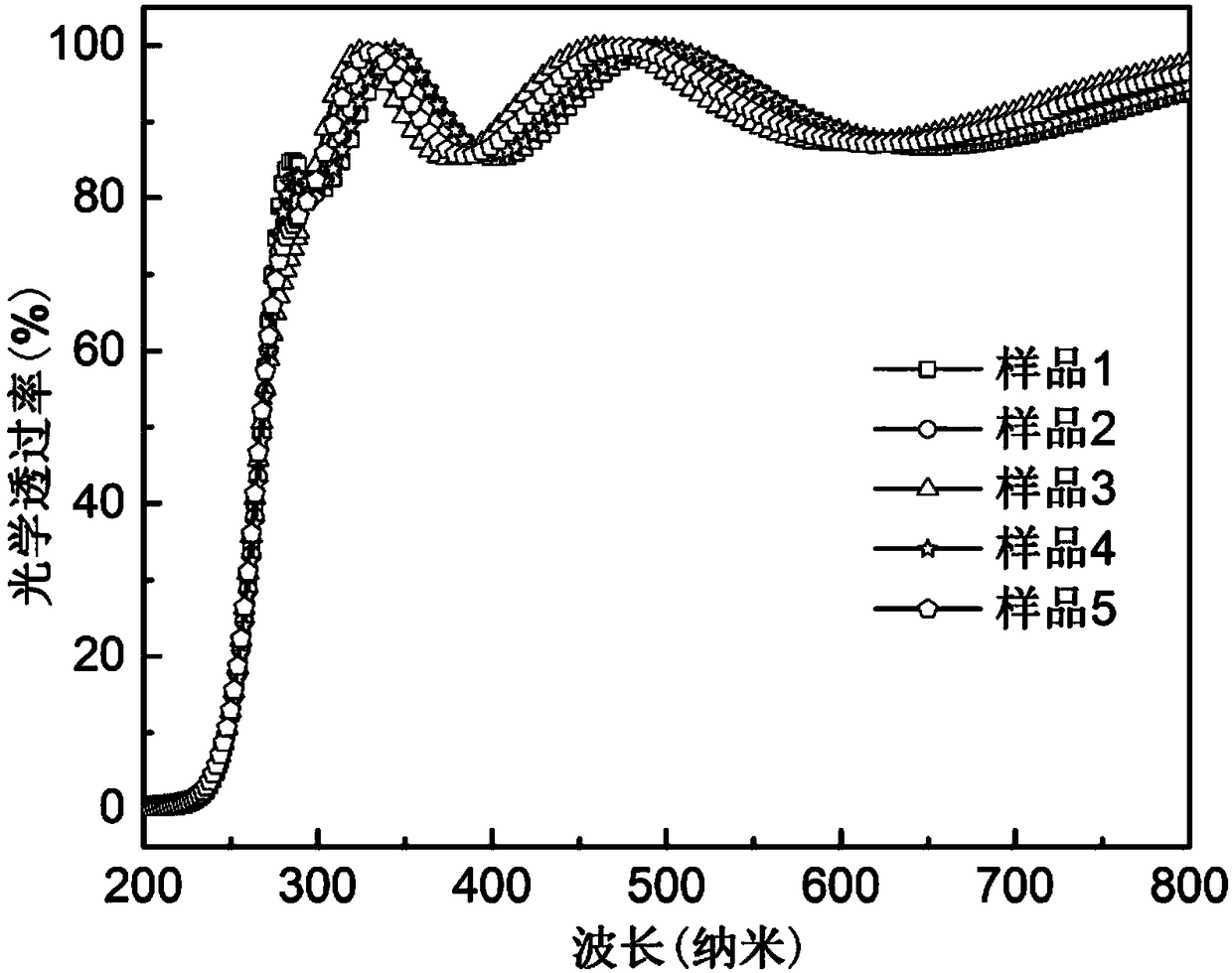
[0050] Prepare amorphous Ga of the present invention according to the method substantially identical with embodiment 1 2 o 3 The solar-blind ultraviolet detector, the difference is that in step 2), after the back vacuum is lowered to less than 5E-5Pa, 0.112 sccm of high-purity oxygen is introduced, and the vacuum in the cavity reaches 1.0E-3Pa. After stabilization, wait for 10 minutes, and when the oxygen flow rate and the vacuum in the chamber are stable, 10 sccm of high-purity argon gas is introduced, and the vacuum in the chamber reaches 1.6E-1Pa, and the Ga 2 o 3 film.

Embodiment 3

[0052] Prepare amorphous Ga of the present invention according to the method substantially identical with embodiment 1 2 o 3 The sun-blind ultraviolet detector, the difference is that in step 2) after the back vacuum is lowered to less than 5E-5Pa, 0.126 sccm of high-purity oxygen is introduced, and the vacuum in the cavity reaches 1.2E-3Pa. After stabilization, wait for 10 minutes. If the oxygen flow rate and the vacuum in the chamber are stable, then 10 sccm of high-purity argon gas is introduced, and the vacuum in the chamber reaches 1.6E-1Pa. Start sputtering Ga 2 o 3 film.


PUM

PropertyMeasurementUnit
Thicknessaaaaaaaaaa
Thicknessaaaaaaaaaa
Thicknessaaaaaaaaaa

Abstract

The invention provides an amorphous Ga2O3 solar-blind ultraviolet detector, and a preparation method and an application thereof. The solar-blind ultraviolet detector comprises a substrate, an amorphous Ga2O3 active layer deposited on the surface of the substrate, and electrodes arranged on the surface of the amorphous Ga2O3 active layer. The solar-blind ultraviolet detector is characterized in that a response speed of the solar-blind ultraviolet detector is less than 1 second. The preparation method comprises the step of introducing oxygen into a vacuum chamber during the deposition process. Through adopting a micro-oxygen flow regulation method, high-purity oxygen is introduced during film growth, resulting in the unexpected increase of the response speed of the device, and the fastest response speed can be 19.1 microseconds, which is the fastest response speed of the amorphous Ga2O3 solar-blind ultraviolet detector reported so far.

Description

technical field [0001] The invention relates to the technical field of electronic devices and photoelectric detection, in particular to an ultrafast response amorphous Ga 2 o 3 Solar-blind ultraviolet detector and its preparation method and application. Background technique [0002] Since the deep ultraviolet light (200-280nm) in the solar-blind band can be almost completely absorbed by the earth’s ozone layer, the background radiation in the atmosphere is close to zero. Low noise and high sensitivity. The two unique advantages of low noise and high sensitivity make solar-blind ultraviolet photodetectors have a very wide application prospect in civilian and military fields, such as space communication, flame monitoring, biomedicine, missile guidance and ozone monitoring, etc. field. [0003] Solar-blind UV detectors are often based on wide-bandgap semiconductor materials. Solar-blind light can excite valence-band electrons in wide-bandgap semiconductors to transition to...

Claims


Application Information

Patent Timeline
IPC IPC(8): H01L31/09H01L31/032H01L31/0376H01L31/18
CPCH01L31/032H01L31/0376H01L31/095H01L31/18Y02E10/50Y02P70/50
Inventor 崔书娟梅增霞张永晖梁会力杜小龙
Owner INST OF PHYSICS - CHINESE ACAD OF SCI
Learn More