Production process and system of ultralow NOx emission of pellet flue gas
A production process and production system technology, applied in the field of pellet production, can solve the problems of substandard discharge and expensive denitrification equipment
- Summary
- Abstract
- Description
- Claims
- Application Information
AI Technical Summary
Problems solved by technology
Method used
Image
Examples
Embodiment 1
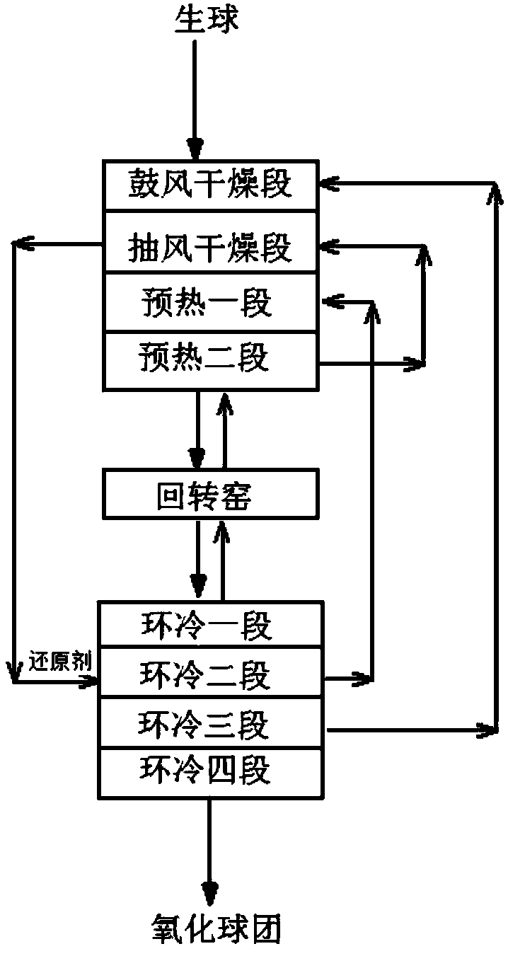
[0119] Such as Figure 6 As shown, a production system for ultra-low NOx emission of pellet flue gas, the system includes: grate machine 1, rotary kiln 2, and annular cooler C. Wherein: according to the process trend, the grate 1 is sequentially provided with a blast drying section UDD, a draft drying section DDD, a preheating section TPH and a preheating section PH. The annular cooler C is sequentially provided with the first stage of annular cooling C1, the second stage of annular cooling C2, the third stage of annular cooling C3 and the fourth stage of annular cooling C4. The tail end of the rotary kiln 2 is connected to the preheating second section PH of the grate 1 and the other end is connected to the annular cooling section C1 of the annular cooler C.
[0120] Wherein: the air outlet C1b of the ring cooling section C1 is connected to the air inlet 201 of the rotary kiln 2 via the first pipeline L1, and the air outlet 202 of the rotary kiln 2 is connected to the air in...
Embodiment 2
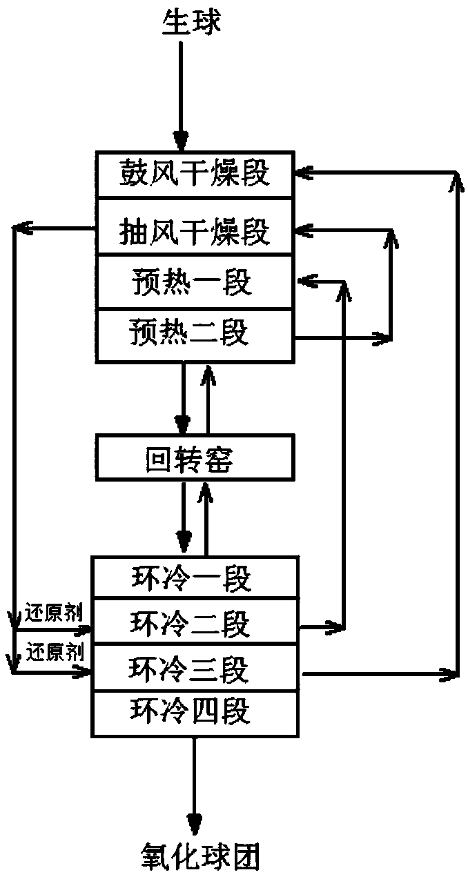
[0124] A production system for ultra-low NOx emission of pellet flue gas, the system includes: a grate machine 1, a rotary kiln 2, and an annular cooler C. Wherein: according to the process trend, the grate 1 is sequentially provided with a blast drying section UDD, a draft drying section DDD, a preheating section TPH and a preheating section PH. The annular cooler C is sequentially provided with a first stage of annular cooling C1, a second stage of annular cooling C2, a third stage of annular cooling C3 and a fourth stage of annular cooling C4. The tail end of the rotary kiln 2 is connected to the preheating second section PH of the grate 1 and the other end is connected to the annular cooling section C1 of the annular cooler C.
[0125] Wherein: the air outlet C1b of the ring cooling section C1 is connected to the air inlet 201 of the rotary kiln 2 via the first pipeline L1, and the air outlet 202 of the rotary kiln 2 is connected to the air inlet 301 of the preheating seco...
Embodiment 3
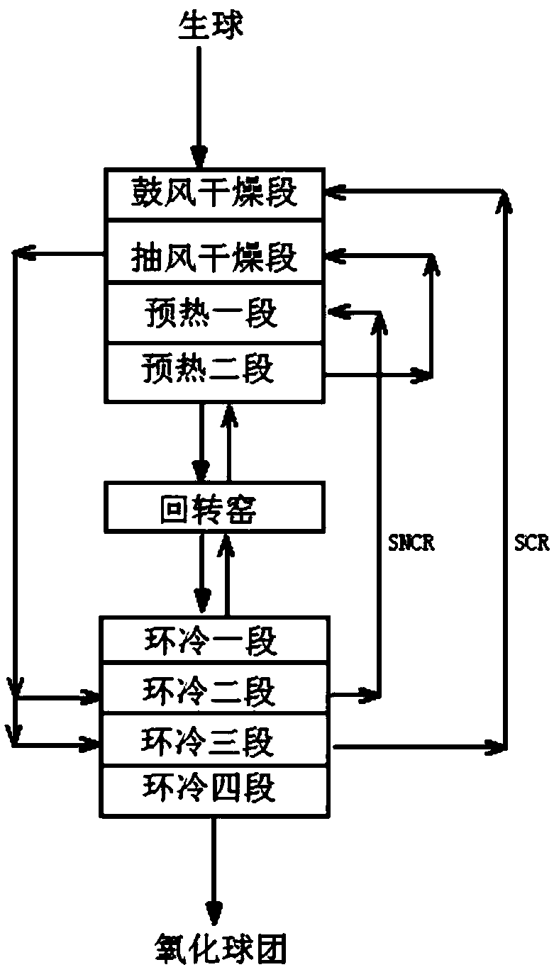
[0129] Such as Figure 7 As shown, embodiment 1 is repeated, except that the sixth pipeline L6 branched out into a seventh pipeline L7. The seventh pipeline L7 is connected to the air inlet C3a of the third ring cooling section C3; at the same time: the second reducing agent injection device 402 is installed at the position of the bottom air box of the third ring cooling section C3.
PUM
| Property | Measurement | Unit |
|---|---|---|
| length | aaaaa | aaaaa |
Abstract
Description
Claims
Application Information
 - R&D
- Intellectual Property
- Life Sciences
- Materials
- Tech Scout
- Unparalleled Data Quality
- Higher Quality Content
- 60% Fewer Hallucinations
Browse by: Latest US Patents, China's latest patents, Technical Efficacy Thesaurus, Application Domain, Technology Topic, Popular Technical Reports.
© 2025 PatSnap. All rights reserved.Legal|Privacy policy|Modern Slavery Act Transparency Statement|Sitemap|About US| Contact US: help@patsnap.com


