Dopant source supply pipeline and chemical vapor deposition system

A technology for supplying pipelines and doping sources, applied in the directions from chemically reactive gases, chemical instruments and methods, circuits, etc., can solve the difficulty of increasing the output concentration control in the output pipeline, complicating the local structure of the output pipeline, and increasing the mass flow rate. The price of the controller is high, and the effect of eliminating the cost of the pipeline, simplifying the structure and simple structure is achieved.

Active Publication Date: 2021-06-04
SUZHOU INST OF NANO TECH & NANO BIONICS CHINESE ACEDEMY OF SCI
View PDF3 Cites 0 Cited by
  • Summary
  • Abstract
  • Description
  • Claims
  • Application Information

AI Technical Summary

Problems solved by technology

[0004] During the doping process of the silicon carbide epitaxial layer, the concentration of the dopant source (the number of atoms or molecules of the dopant source per unit volume) varies widely, and needs to be within 10 15 cm -3 ——10 20 cm -3 The existing dopant source supply pipeline meets the needs of large-span adjustment of the dopant source concentration delivered to the reaction chamber through multiple pipelines with mass flow controllers with different flow ranges, but Since the adjustment range of each mass flow control is limited, the number of mass flow controllers required for such a large-span concentration adjustment is also very large, and the price of mass flow controllers is relatively high, which causes pipeline The cost is greatly increased, and it also complicates the local structure of the output pipeline; in addition, the complicated output pipeline also increases the difficulty of controlling the output concentration
[0005] Moreover, in the existing aluminum-nitrogen doping process, two sets of independent pipelines are usually required to supply the aluminum source and the nitrogen source respectively, which further complicates the structure of the pipeline, resulting in a larger structure of the epitaxial growth equipment. While increasing the cost of equipment

Method used


Image

  • Dopant source supply pipeline and chemical vapor deposition system
  • Dopant source supply pipeline and chemical vapor deposition system
  • Dopant source supply pipeline and chemical vapor deposition system

Examples


Embodiment Construction

[0033] Objects, advantages and features of the present invention will be illustrated and explained by the following non-limiting description of preferred embodiments. These embodiments are only typical examples of applying the technical solutions of the present invention, and all technical solutions formed by adopting equivalent replacements or equivalent transformations fall within the protection scope of the present invention.

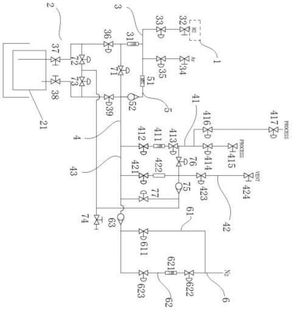
[0034] The invention discloses a doping source supply pipeline, which is mainly used for the doping of aluminum and nitrogen in the silicon carbide epitaxial layer, as shown in the attached figure 1 As shown, it includes a carrier gas source 1, and also includes a main gas circuit 4, a dilution pipeline 5, an organometallic source supply pipeline 2 and / or a nitrogen gas supply pipeline 6, and the main gas circuit 4 is connected to the dilution pipeline 5 , organometallic source supply line 2 and / or nitrogen supply line 6, and the main gas line 4 cont...


PUM


Abstract

The invention discloses a dopant source supply pipeline and a chemical vapor deposition system. The dopant source supply pipeline includes a carrier gas source and a water bath system for containing an organic metal source, and also includes a carrier gas delivery pipeline connected to the carrier gas and a water bath system to feed the carrier gas into the organometallic source; the organometallic source gas delivery pipeline connects the water bath system to the reaction chamber and the waste treatment system, and the first branch connected to the reaction chamber has and only A first mass flow controller; a dilution pipeline, a main pipeline connecting the carrier gas source and the organometallic source gas delivery pipeline, for diluting the concentration of the dopant source gas in the main pipeline. The present invention only needs one mass flow controller to meet the large-span adjustment requirement of dopant source gas concentration, saves the pipeline cost caused by multiple mass flow controllers, and the pipeline structure in the output area is more concise; at the same time , the concentration adjustment is more convenient.

Description

technical field [0001] The invention relates to the field of epitaxial growth of silicon carbide, in particular to a dopant source supply pipeline and a chemical vapor deposition system. Background technique [0002] Silicon carbide is the third generation wide bandgap semiconductor material with wide bandgap, high breakdown voltage, high thermal conductivity, high electron saturation drift rate, high electron mobility, small dielectric constant, strong radiation resistance, and high chemical stability It is the key material for manufacturing high temperature, high frequency, high power, radiation resistance, non-volatile storage devices and optoelectronic integrated devices. [0003] Silicon carbide power electronic devices have the characteristics of high conversion efficiency, high temperature resistance, and radiation resistance, and have gradually replaced silicon devices in the fields of power conversion, solar photovoltaics, electric vehicles, and high-efficiency moto...

Claims


Application Information

Patent Timeline
Patent Type & Authority Patents(China)
IPC IPC(8): H01L21/205C30B29/36C30B25/14C30B25/16
CPCC30B25/14C30B25/165C30B29/36
Inventor 鞠涛张立国李哲范亚明张泽洪张宝顺
Owner SUZHOU INST OF NANO TECH & NANO BIONICS CHINESE ACEDEMY OF SCI
Why Eureka
Try Eureka