Binary X-ray energy selective device and preparing method thereof

A binarization and energy selection technology, which is applied in the field of X-ray energy selection, can solve the problems of high energy through noise, large spatial solid angle, poor maintainability, etc., and achieve the effect of improving the signal-to-noise ratio

Active Publication Date: 2019-04-16
LASER FUSION RES CENT CHINA ACAD OF ENG PHYSICS
View PDF7 Cites 2 Cited by
  • Summary
  • Abstract
  • Description
  • Claims
  • Application Information

AI Technical Summary

Problems solved by technology

However, the main problems of this method are: 1) Due to the non-coaxial optical path, there are differences in viewing angles between different channels; 2) The grazing incidence angle is generally less than 10°. In order to cover all incident X-rays, the mirror surface must be large enough. The large spatial solid angle increases the difficulty of expanding the number of channels. On the other hand, the consistency of the energy spectrum in different regions of the obtained image is poor; 3) The optical path structure is complex, and there are problems such as high assembly difficulty and poor maintainability.
However, the microchannel plate device is mainly used to achieve electronic gain amplification. There is no optical unit in its structure that can realize high-energy X-ray absorption. The high-energy components in the incident light may penetrate through the multi-layer channel wall to form channel crosstalk and reduce the imaging spatial resolution. Or pass directly through this device and be recorded by detectors or image recording equipment, forming high-energy direct-through noise

Method used


Image

  • Binary X-ray energy selective device and preparing method thereof
  • Binary X-ray energy selective device and preparing method thereof
  • Binary X-ray energy selective device and preparing method thereof

Examples


preparation example Construction

[0034] The embodiment of the present invention also provides a method for preparing the above-mentioned binary X-ray energy selection device, which includes:

[0035] S1. The reflecting element monofilament and the absorbing element monofilament are stacked and combined in the sleeve to obtain a multifilament rod;

[0036] Wherein, the sleeve and the absorption element monofilament are both made of corrosion-resistant materials, and the reflection element monofilament includes a shell and an inner core sheathed with each other, the shell is made of corrosion-resistant material, and the inner core is made of corrosion-resistant material.

[0037] Further, in actual operation, the outer tube made of corrosion-resistant material and the core made of corrosion-resistant material can be used to combine to form a core rod assembly, and then the reflector monofilament can be prepared by hot drawing. At the same time, the outer tube made of corrosion-resistant material and the core body made...

Embodiment 1

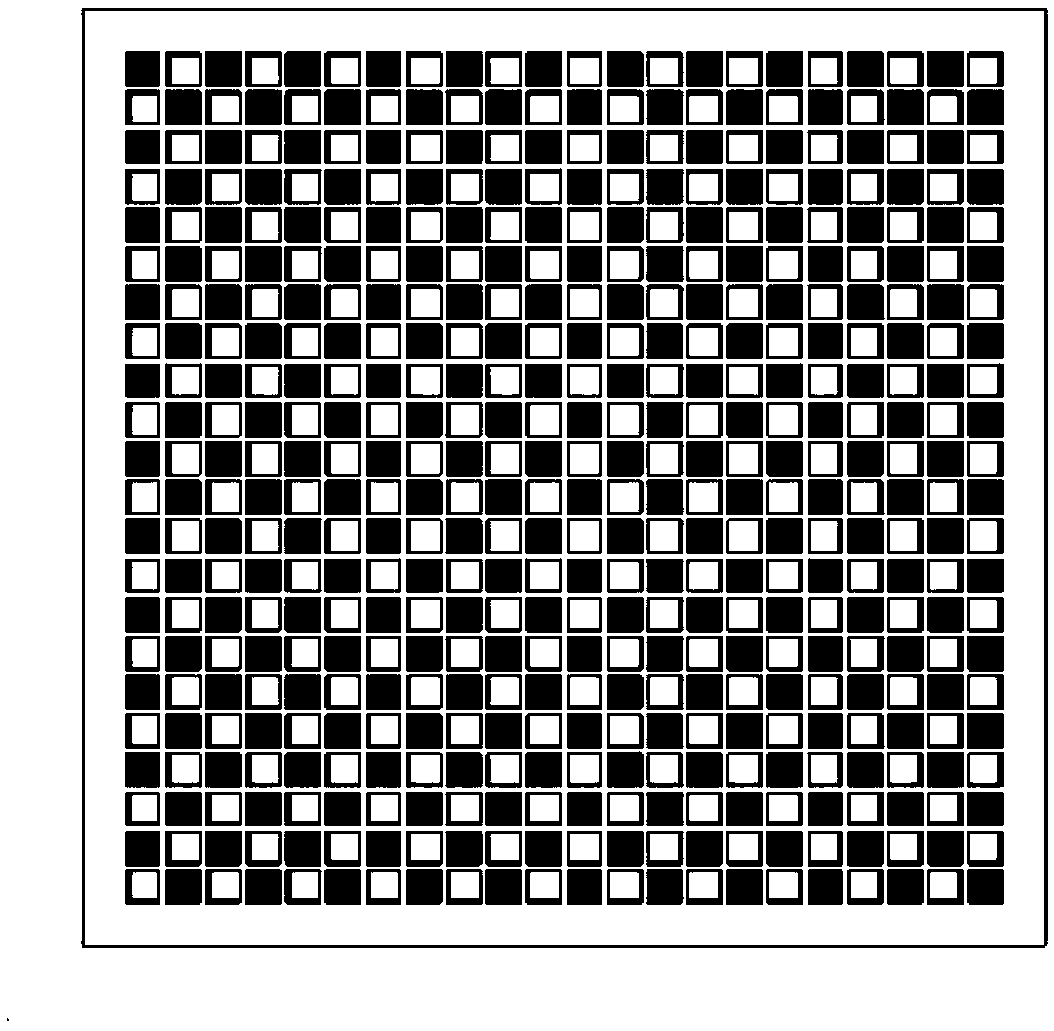
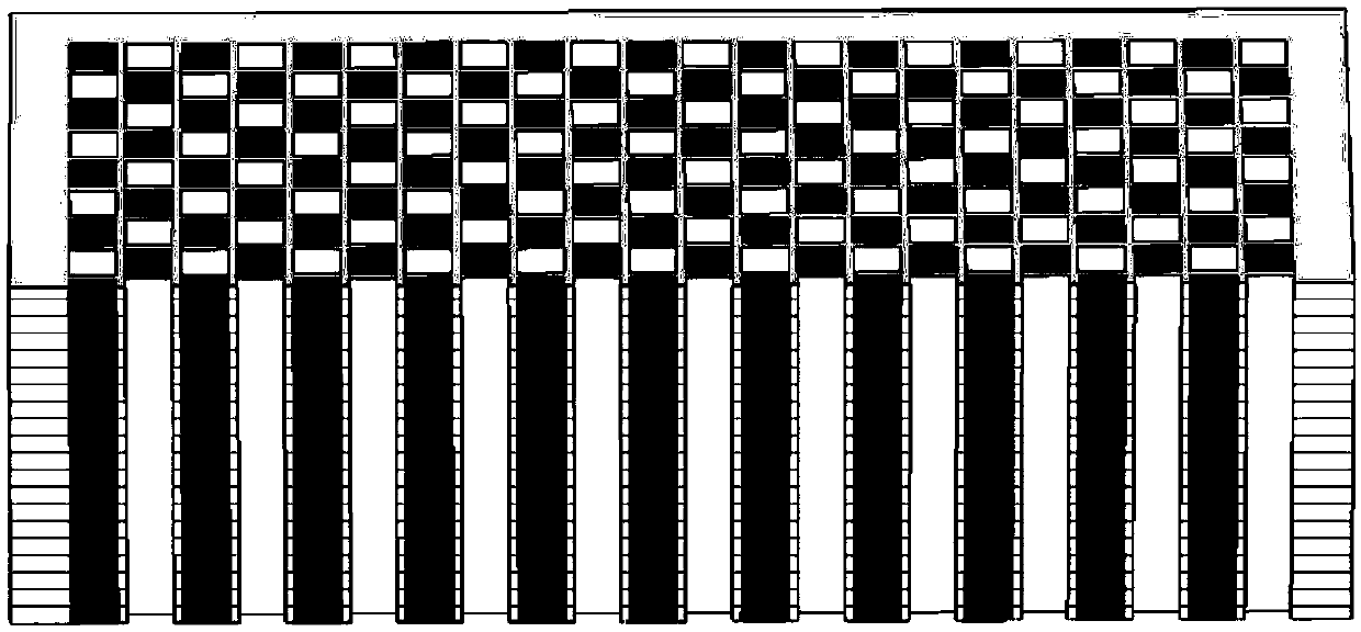
[0054] This embodiment provides a binary X-ray energy selective device, refer to figure 1 with figure 2 As shown, it is composed of multiple X-ray reflecting elements and multiple X-ray absorbing elements stacked alternately.

[0055] Among them, the X-ray reflector is a hollow structure, and its inner wall is provided with an Ag plating layer. The height is 100 μm, the cross section is square, and the side length is 5 μm.

[0056] The X-ray absorber has a solid structure, and the PbO content is 35wt%. The height is 100 μm, the cross section is square, and the side length is 5 μm.

[0057] The preparation method of the binary X-ray energy selective device includes:

[0058] S1. Stack and combine the reflecting element monofilament and the absorbing element monofilament in a square mold to obtain a multifilament rod;

[0059] Among them, the casing tube and the absorption element monofilament are made of high-lead silicate glass containing alkali metal oxides, and the reflector monofi...

Embodiment 2

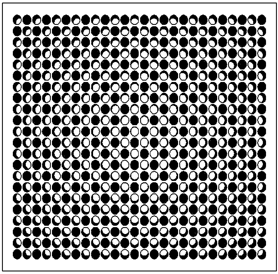
[0065] This embodiment provides a binary X-ray energy selective device, refer to image 3 with Figure 4 As shown, it is composed of multiple X-ray reflecting elements and multiple X-ray absorbing elements stacked alternately.

[0066] Among them, the X-ray reflector is a hollow structure, and its inner wall is provided with an Au plating layer. The height is 4000μm, the cross section is circular, and the diameter is 20μm.

[0067] The X-ray absorber has a solid structure, and the content of PbO is 40wt%. The height is 4000μm, the cross section is circular, and the diameter is 20μm.

[0068] The preparation method of the binary X-ray energy selective device includes:

[0069] S1. Stack and combine the reflecting element monofilament and the absorbing element monofilament in a square mold to obtain a multifilament rod;

[0070] Among them, the sleeve and the absorption element monofilament are both made of high-lead silicate glass containing alkaline earth metal oxides. The reflector m...


PUM


Abstract

The invention discloses a binary X-ray energy selective device, and relates to the field of X-ray energy selection. The binary X-ray energy selective device is formed by regularly piling up optical units which show binary distribution on transmission of X-rays, and particularly comprises columnar X-ray reflection elements and columnar X-ray absorbing elements. The X-ray reflection elements are ofa hollow structure, the inner walls of the X-ray reflection elements are plated with reflection layers, low-energy X-rays can be transmitted in the X-ray reflection elements and reflected by the innerwall of a channel, and thus an energy selection effect with low pass and high resistance is achieved. The X-ray absorption elements are of a solid structure and are doped with X-ray absorbents and can absorb high-energy X-rays to improve the energy selection efficiency and signal-to-noise ratios for imaging and detection. According to a preparing method of the binary X-ray energy selective device, reflection element monofilaments and absorption element monofilaments are piled up and combined in a sleeve to obtain a multifilament rod; the multifilament rod is subjected to thermal stretching, cutting, thermal fusion, corrosion, metal deposition and the like, and thus the binary X-ray energy selective device is obtained. The binary X-ray energy selective device is easy and convenient to operate, the requirement for equipment is low, the controllability of the preparing process is high, and the precision is high.

Description

Technical field [0001] The invention relates to the field of X-ray energy selection, in particular to a binary X-ray energy selection device and a preparation method thereof. Background technique [0002] In the research fields of high-energy-density physics based on laser-plasma interaction, laboratory astrophysics, inertial confinement fusion, etc., acquiring time, space and spectral information of X-ray radiation through detection or imaging is to study plasma An important means of the state of matter. Generally, the X-ray radiation of plasma is a broad-spectrum radiation formed by the processes of Bremsstrahlung, line radiation, and composite radiation. However, to realize the fine characterization of the plasma state, the X-ray radiation in a specific spectral range must be independent Detection or imaging. For example, in the research of indirect drive inertial confinement fusion, independent imaging of the N-band (0.5-1keV) and M-band (1.6-3.5keV) radiation of the black ...

Claims


Application Information

Patent Timeline
Patent Type & Authority Applications(China)
IPC IPC(8): G21K1/06G21K1/10
CPCG21K1/067G21K1/10
Inventor 曹柱荣王强强陈韬邓克立邓博袁铮黎宇坤
Owner LASER FUSION RES CENT CHINA ACAD OF ENG PHYSICS
Why Eureka
Try Eureka