High salinity wastewater incineration desalting system and treatment method thereof

A high-salt wastewater and high-temperature flue gas technology, which is applied in the direction of combustion methods, water/sewage treatment, heating water/sewage treatment, etc., can solve the problems of high investment cost, uncontrollable oxygen concentration, and non-recoverable heat energy, etc. Simple, convenient for industrial application, and the effect of improving the precipitation rate

Pending Publication Date: 2019-05-21
JIANGSU JINNIU ENVIRONMENTAL ENG EQUIP
View PDF10 Cites 5 Cited by
  • Summary
  • Abstract
  • Description
  • Claims
  • Application Information

AI Technical Summary

Problems solved by technology

[0002] At present, it is inevitable to produce a large amount of high-salt wastewater in industrial production. The traditional process generally adopts the method of incinerating high-salt wastewater. The existing problems are: 1. The saline wastewater must be cooled by rapid cooling after incineration. The traditional method is to use a large amount of water for mixing and cooling, and the quenched water needs to be discharged to the sewage treatment plant for subsequent treatment, which greatly wastes water resources and the subsequent treatment process is complicated, and the investment cost is high; 2. During the incineration process, If the incineration temperature is too high, the salt will melt, and the molten salt will penetrate into the refractory material of the incinerator, causing the refractory material to be peeled off layer by layer, and the life of the refractory material will be greatly shortened; 3. The heat energy after incineration cannot be recovered , high energy consumption; 4. Molten salt and other substances incinerated at high temperature will produce insoluble matter, which will block equipment and systems; 5. The salt after quenching will become floating dust and cause serious pollution to the surrounding environment
Its technical solution removes a large amount of precipitated salt through primary incineration, then removes salt-containing dust through a dust removal device, and then enters a secondary incinerator for re-incineration. The system concept is correct, but it cannot control the temperature of the incoming high-temperature flue gas. The oxygen concentration in the flue gas is also uncontrollable, causing the precipitated salt to form a molten state easily, and cannot enter the subsequent dust removal equipment for dust removal at all, and the precipitated salt of the flue gas incinerated by the primary incinerator enters the dust removal device together with the organic gas For dust removal, the dust removal device cannot load such a large salt content at all, and the salt-containing dust particles cannot be separated and discharged, causing the secondary incinerator to still have problems with the existing technology, which needs to be improved

Method used


Image

  • High salinity wastewater incineration desalting system and treatment method thereof
  • High salinity wastewater incineration desalting system and treatment method thereof
  • High salinity wastewater incineration desalting system and treatment method thereof

Examples


Embodiment 1

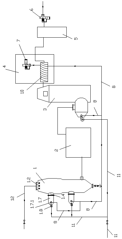
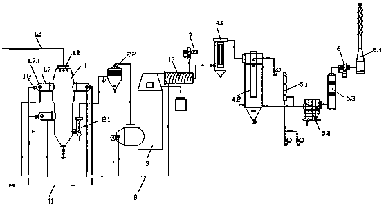
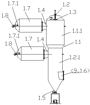
[0018] Example 1: A high-salt wastewater incineration and desalination system, including a drying reactor 1, a desalination device 2, a secondary combustion chamber 3, a waste heat recovery device 4, and a purification and discharge device 5. The air outlet of the drying reactor 1 is connected by a pipeline to remove The salt device 2, the air outlet pipe of the desalination device 2 is connected to the secondary combustion chamber 3, and the air outlet pipe of the secondary combustion chamber 3 is connected to the waste heat recovery device 4. The system is pumped into a vacuum and negative pressure state. The drying reactor 1 includes a vertical cylinder 1.1, a high-salt wastewater inlet 1.2 installed on the top of the vertical cylinder 1.1, and a pressurized atomization device 1.3 is installed on the high-salt wastewater inlet 1.2. The high-temperature flue gas inlet 1.4 on the vertical cylinder 1.1, the salt outlet 1.5 at the bottom of the vertical cylinder 1.1, the organic...

Embodiment 2

[0019] Embodiment 2: With reference to Embodiment 1, other structures remain unchanged, the high-temperature flue gas inlet 1.4 of the drying reactor 1 is opened tangentially along the vertical cylinder body 1, so that the high-temperature flue gas is formed along the inner wall of the vertical cylinder body 1.1 Spiral downward turbulence, desalination device 2 includes cyclone dust collector 2.1, high temperature cotton dust collector 2.2, waste heat recovery device 4 includes air heat exchanger 10, air inlet of air heat exchanger 10 is connected to oxygen supply fan 7, and The waste heat steam generator 4.1 connected to the flue gas outlet of the air heat exchanger 10, and the semi-dry quenching tower 4.2; the purification and discharge device 5 includes a mixing reactor 5.1, a bag filter 5.2, a neutralization scrubber 5.3, a smoke exhaust fan 6, an exhaust Inflator 5.4 etc.

Embodiment 3

[0020] Embodiment 3, with reference to Embodiment 2, other structures remain unchanged, the vertical cylinder body 1.1 is provided with an upper large-diameter section 1.1.1 and a lower small-diameter section 1.1.2, and high-temperature flue gas is provided on the cylinder wall of each cylinder body Air inlet 1.4, the high-temperature flue gas inlet 1.4 is provided with one around the center of each vertical cylinder 1.1, the organic gas outlet 1.6 is connected to the outlet pipe 9, and the connecting end of the outlet pipe 9 extends into the vertical cylinder 1.1, The port is close to the center of the vertical cylinder 1.1. The height from the bottom end of the pressurized atomization device 1.3 to the nearest high-temperature flue gas inlet 1.4 is 300mm~600mm. The range of height and diameter of the large and small diameter segments (1.1.1, 1.1.2) and the proportional relationship between them are 3 to 2.


PUM

PropertyMeasurementUnit
clearance rateaaaaaaaaaa

Abstract

The invention provides a high salinity wastewater incineration desalting system and a treatment method thereof. The high salinity wastewater incineration desalting system comprises a drying reactor, adesalting device, a secondary combustion chamber, a waste heat recovery device and a purification and emission device; an air outlet pipeline of the drying reactor is connected with the desalting device; an air outlet pipeline of the desalting device is connected with the secondary combustion chamber; an air outlet pipeline of the secondary combustion chamber is connected with the waste heat recovery device; the purification and emission device comprises a smoke exhaust fan; the drying reactor comprises a vertical cylinder body , a high salinity wastewater inlet, a supercharged atomization device, a high temperature flue gas inlet, a salt outlet and an organic gas outlet, wherein the high salinity wastewater inlet is formed in the top end of the vertical cylinder body; the supercharged atomization device is arranged at the inlet; the high temperature flue gas inlet is formed in the vertical cylinder body; the salt outlet is formed in the bottom end of the vertical cylinder body; the organic gas outlet is formed in the side wall, close to the bottom end, of the vertical cylinder body; the high temperature flue gas inlet is formed in the tangential direction of the vertical cylinderbody so that high temperature flue gas forms a spiral downward turbulent flow along the internal wall of the vertical cylinder body; the high temperature flue gas inlet is connected with a heating furnace and a natural gas burning machine; and an oxygen supplementing air inlet is formed in the heating furnace.

Description

technical field [0001] The invention relates to the field of high-salt wastewater treatment, in particular to an incineration method for treating high-salt wastewater. Background technique [0002] At present, it is inevitable to produce a large amount of high-salt wastewater in industrial production. The traditional process generally adopts the method of incinerating high-salt wastewater. The existing problems are: 1. The saline wastewater must be cooled by rapid cooling after incineration. The traditional method is to use a large amount of water for mixing and cooling, and the quenched water needs to be discharged to the sewage treatment plant for subsequent treatment, which greatly wastes water resources and the subsequent treatment process is complicated, and the investment cost is high; 2. During the incineration process, If the incineration temperature is too high, the salt will melt, and the molten salt will penetrate into the refractory material of the incinerator, c...

Claims


Application Information

Patent Timeline
Patent Type & Authority Applications(China)
IPC IPC(8): C02F1/04C02F1/12C02F1/16F23G7/06F23J15/02F23J15/04F23J15/06
CPCY02A20/124Y02E20/30
Inventor 孙明华尚文君王兆民
Owner JIANGSU JINNIU ENVIRONMENTAL ENG EQUIP
Why Eureka
Try Eureka