Solar cell with double photoelectric conversion function

A solar cell and photoelectric conversion technology, applied in photovoltaic power generation, circuits, electrical components, etc., can solve problems such as scarcity, achieve low price, improve photoelectric conversion performance, and simple synthesis process

Pending Publication Date: 2019-05-31
HEBEI UNIVERSITY OF SCIENCE AND TECHNOLOGY +1
View PDF3 Cites 2 Cited by
  • Summary
  • Abstract
  • Description
  • Claims
  • Application Information

AI Technical Summary

Problems solved by technology

However, the research on further improving the photoelectric conversion efficiency by combining the dual photoelectric conversion functions of quantum dots and perovskites with nanowire carrier transport substrates is very scarce.

Method used


Image

  • Solar cell with double photoelectric conversion function
  • Solar cell with double photoelectric conversion function
  • Solar cell with double photoelectric conversion function

Examples


Embodiment 1

[0024] The preparation process of the solar cell is as follows: (1) spin-coating TiO on transparent conductive glass 2 Seed layer, after high-speed 2000r / min spin coating, the substrate was calcined in a muffle furnace at 450°C; (2) TiO was prepared by hydrothermal method 2 For nanorods, add an appropriate amount of tetrabutyl titanate to a mixture of equal volume ratios of water and concentrated hydrochloric acid, stir to form a sol, transfer it to a polytetrafluoroethylene reactor, place it in a 170°C oven for hydrothermal reaction for 90 minutes, and then After natural drying, it was calcined in a muffle furnace at 300°C; (3) the substrate was treated in an aqueous solution of titanium tetrachloride, dried and calcined at 500°C in a muffle furnace; (4) by continuous ion spin coating method To prepare the quantum dot layer, the GaCl 3 , CuCl 2 、Na 2S was made into a solution with a concentration ratio of 1:1:2, and was spin-coated on the substrate in sequence, and the abo...

Embodiment 2

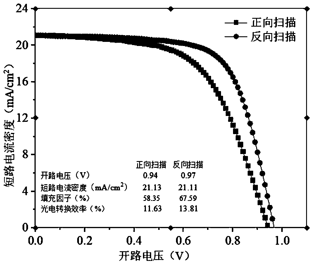
[0026] The preparation process of the solar cell is the same except the quantum dot preparation process in step 4 of Example 1. The scanning electron microscope photos of the front and cross-section of titanium dioxide nanowires, and the data of the photoelectric conversion efficiency of the battery are shown in image 3 and Figure 4 .

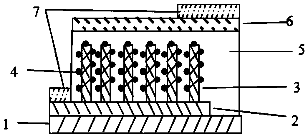
[0027] In a two-dimensional ordered array (n-type / p-type) as the carrier transport layer, quantum dots and halide perovskite as dual photoelectric conversion materials. Quantum dots have the advantages of high extinction coefficient, simple synthesis process, quantum confinement effect, multi-exciton effect, and mainly absorb short-wavelength bands of visible light, which are compatible with the high extinction coefficient, double-carrier transport properties, and long-carrying current of perovskite materials. The advantages of sub-transmission distance, less defect state density and full-band absorption of visible light are combined to imp...


PUM


Abstract

The invention discloses a solar cell with a double photoelectric conversion function. The cell structurally comprises a substrate, a transparent conducting layer, a 2D ordered array carrier transmission layer (n type / p type), a quantum dot layer, a perovskite photoelectric conversion layer, a carrier transmission layer (correspondingly p type / n type) and a conductive electrode. The solar cell withthe double photoelectric conversion function is characterized in that a 2D ordered array serves as the carrier transmission layer, and quantum dots and a perovskite organic metal halide serve as a double photoelectric conversion material. The quantum dots have the advantages of a high delustering coefficient, a simple synthesis process, a quantum domain limit effect and a multi-exciton effect, and mainly absorbing intermediate and short wave segment from visible light; the advantages of the quantum dots are combined with advantages including a high delustering coefficient, double-carrier transmission property, long carrier transmission distance, low defect mode density and absorbing all wave bands of visible light of the perovskite halide material; and thus, the photoelectric conversion performance is improved, the structure preparation technology is simple, the cost is low, and the application prospects are wider.

Description

technical field [0001] The patent of the present invention relates to the field of semiconductor optoelectronic sensor devices, in particular to a solar cell with dual photoelectric conversion functions. Background technique [0002] With the development of human economy and society, energy and environmental issues have become increasingly prominent, and it is imperative to develop a clean, efficient, and low-cost renewable energy. As a clean energy, solar energy is of great significance to reducing environmental pollution and delaying global warming. A solar cell is a semiconductor device that can directly convert light energy into electrical energy. It has the advantages of safety and pollution-free, long cycle life, and easy disassembly. From the market to daily necessities such as automobiles, street lamps, color TVs, and air conditioners, it has gradually moved towards commercialization and industrialization. [0003] Conventional solar cells are based on nanoparticle...

Claims


Application Information

Patent Timeline
Patent Type & Authority Applications(China)
IPC IPC(8): H01L51/42H01L51/48B82Y20/00
CPCY02E10/549
Inventor 郝彦忠栗靖琦赵晋津刘金喜苏晓赵泽文张颖
Owner HEBEI UNIVERSITY OF SCIENCE AND TECHNOLOGY
Why Eureka
Try Eureka