Method of regenerating used denitration catalyst

A denitrification catalyst and catalyst technology, applied in the direction of catalyst regeneration/reactivation, physical/chemical process catalysts, chemical instruments and methods, etc., can solve the problems of reduced catalyst strength, difficult chemical solution treatment, easy residual ash components, etc., to achieve improved The effect of reuse times

Pending Publication Date: 2019-07-30
MITSUBISHI HEAVY IND LTD
View PDF12 Cites 1 Cited by
  • Summary
  • Abstract
  • Description
  • Claims
  • Application Information

AI Technical Summary

Problems solved by technology

[0010] Usually, the regeneration method of the denitration catalyst using a chemical solution such as an aqueous inorganic acid solution, an aqueous fluoride solution, or an aqueous alkali solution has the following problems: sometimes neutralization treatment is required after cleaning with the chemical solution; Reduced strength of catalyst; sometimes accompanied by difficulties in handling of chemical solutions, etc.
On the other hand, the regeneration method of the denitration catalyst based on physical removal with a brush or the like has problems such as the following problems: ash components are likely to remain in places where the brush cannot reach
In this way, the regeneration methods proposed in the past have advantages and disadvantages in terms of practicality.

Method used


Image

  • Method of regenerating used denitration catalyst
  • Method of regenerating used denitration catalyst
  • Method of regenerating used denitration catalyst

Examples


manufacture example 1

[0075] Production example 1 (catalyst 1)

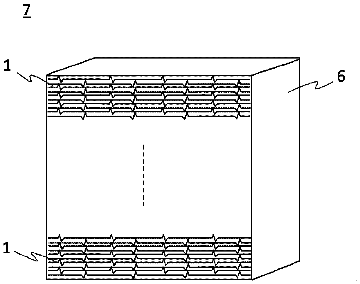
[0076] Prepare a plate-shaped denitration catalyst element (catalyst 1) having a plate material comprising a metal strip with a thickness of 0.7 mm and a catalyst layer carried on the plate material by processing a SUS430 steel plate with a thickness of 0.2 mm. 0 ). The catalyst layer contains: Titanium oxide (TiO 2 ), tungsten oxide (WO 3 ) and vanadium oxide (V 2 o 5 ) catalyst component, 15% by mass of silica-alumina-based inorganic fibers relative to the catalyst component, and 8% by mass of the binder (SiO 2 ). Proceed to Catalyst I 0 Elemental quantitative analysis of surfaces. from Catalyst I 0 Catalyst pellets of 20 mm x 100 mm were cut out. It was used to determine the initial denitrification rate. The results are shown in Table 2.

[0077] The plate-shaped denitration catalyst element (catalyst I 0 ) are stacked and accommodated in a unit frame to obtain a catalyst unit. The catalyst unit was installed in the de...

manufacture example 2

[0078] Production example 2 (catalyst II)

[0079] Prepare a plate-shaped denitration catalyst element (catalyst II 0 ). The catalyst layer contains: titanium oxide (TiO 2 ), molybdenum oxide (MoO 3 ) and vanadium oxide (V 2 o 5 ) catalyst component, 15% by mass of silica-alumina-based inorganic fibers relative to the catalyst component, and 2% by mass of the binder (SiO 2 ). Proceed to Catalyst II 0 Elemental quantitative analysis of surfaces. from Catalyst II 0 Catalyst pellets of 20 mm x 100 mm were cut out. It was used to determine the initial denitrification rate. The results are shown in Table 2.

[0080] The plate-shaped denitration catalyst element (catalyst II 0 ) are stacked and accommodated in a unit frame to obtain a catalyst unit. The catalyst unit is installed in the denitrification device of PRB coal-fired boiler exhaust gas in the United States and used for denitrification treatment for about 2 years. From this catalyst unit, the used plate-shaped...

reference example 1

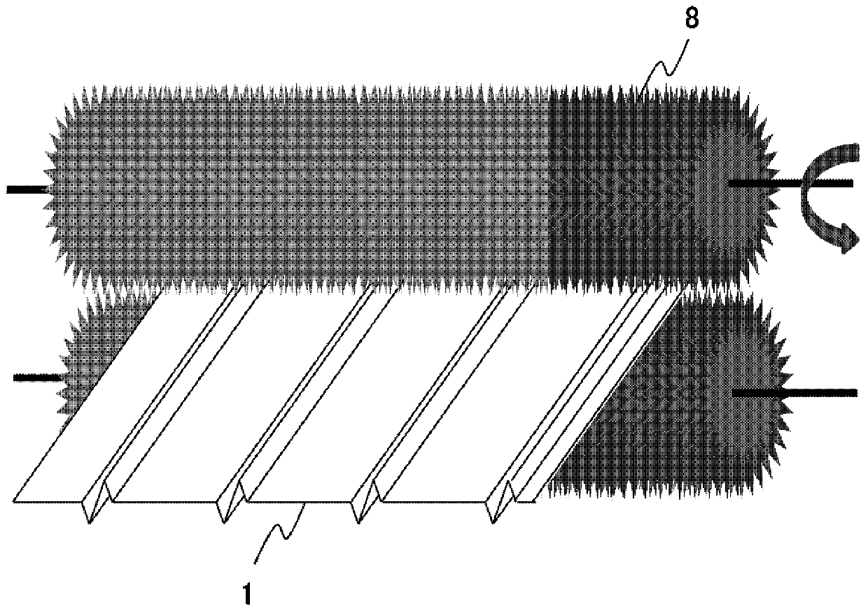
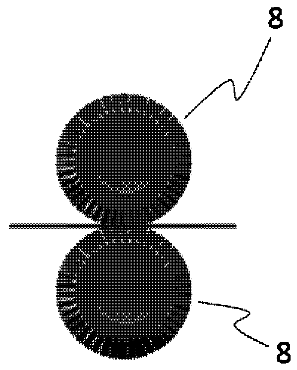
[0085] from Catalyst I 1 Catalyst sheets of 100 mm x 100 mm were cut out. The catalyst sheet was immersed in a 60°C, 5% by mass aqueous oxalic acid solution. The surface of the catalyst sheet was brushed 20 times with a resin brush (bristles: made of resin, diameter: 200 μm / bristle, hair length: 10 mm) while immersed in the oxalic acid aqueous solution. The catalyst sheet was allowed to dry naturally. Quantitative analysis of elements on the surface of the obtained cleaned catalyst sheet was performed to calculate the coverage. The results are shown in Table 3. Coverage is drastically reduced.


PUM


Abstract

A method for regenerating a used denitration catalyst including: brushing, using a brush, the surface of a plate-shaped denitration catalyst element comprising a plate material, which alternately hasflat parts and ridge spacer parts, and a catalyst layer, which is carried by the plate material and which contains titanium oxide as the main component, and having a compound containing Si, Al, or Caadhered thereto by a flue gas denitration process, the surface of the plate-shaped denitration catalyst element being brushed while water or an aqueous acid solution is adhered to the surface of the plate-shaped denitration catalyst element; and impregnating the plate-shaped denitration catalyst element which has been brushed using the brush with a liquid containing a catalytically active component.

Description

technical field [0001] The invention relates to a regeneration method of a used denitration catalyst. More specifically, the present invention relates to a method for regenerating a used denitration catalyst degraded by adhesion of a compound containing Si, Al, or Ca. Background technique [0002] The denitration performance of denitration catalysts used for a long time in the denitration treatment of combustion exhaust gas is greatly reduced by the adhesion of alkali components, arsenic, phosphorus, etc., or the adhesion of silica, alumina, calcium compounds, etc. From the viewpoint of effective utilization of resources, it has been proposed to regenerate a used denitration catalyst whose denitration performance has deteriorated and reuse it in the denitration treatment. [0003] For example, Patent Document 1 discloses a method for regenerating a denitration catalyst. The method includes abrasively removing the surface layer of the granular denitration catalyst with a dru...

Claims


Application Information

Patent Timeline
Patent Type & Authority Applications(China)
IPC IPC(8): B01J38/00B01D53/96B01J23/30B01J23/92B01J38/60B01J38/62
CPCB01D53/96B01J23/30B01J23/92B01J38/00B01J38/60B01J38/62B01D53/8621B01D53/885B01J23/22B01J23/28
Inventor 今田尚美松山琴衣加藤泰良
Owner MITSUBISHI HEAVY IND LTD
Why Eureka
Try Eureka