Synchronous sludge treatment system of membrane bioreactor and sludge treatment method thereof

A membrane bioreactor, sludge treatment technology, applied in biological water/sewage treatment, water/sludge/sewage treatment, chemical instruments and methods, etc. Expensive and other problems, to achieve good economic and environmental benefits, save equipment and manpower, and not easy to secondary pollution.

Pending Publication Date: 2019-08-02
EAST CHINA NORMAL UNIV
View PDF4 Cites 2 Cited by
  • Summary
  • Abstract
  • Description
  • Claims
  • Application Information

AI Technical Summary

Problems solved by technology

The formation of biofilm is not only an important part of membrane fouling itself, but also leads to an increase in the viscosity of the membrane to the mixture, making it easier for particulate matter in sewage to adsorb on the membrane surface, thereby further causing membrane fouling
For solving the serious problem of membrane fouling, many methods have emerged, such as the Chinese patent document "A Method for Alleviating Membrane Fouling in Membrane Bioreactors" (publication number CN 102491505 A, published on June 13, 2012) A method for alleviating membrane fouling in a submerged membrane bioreactor, the method adds a water-soluble iron compound to the feed water before the membrane bioreactor, and the addition amount is 10 to 150 mg/L in terms of ferric ions, It overcomes the disadvantage of adding water-soluble iron compounds to the mixed solution in the prior art, which causes the unsatisfactory effect of actually mitigating membrane fouling, and can significantly reduce membrane fouling. The average growth rate of the membrane pressure difference can be reduced by 8 to 12%. The growth rate of the membrane pressure difference, but the dosage of the agent is large, and the processing cost is high
[0005] The Chinese patent document "A Preparation and Application for Preventing MBR Membrane Fouling" (publication number CN 107899428 A, published on April 13, 2018) discloses a preparation and application for preventing membrane fouling of membrane bioreactors. The preparation includes 50-60% of signal molecule

Method used


Image

  • Synchronous sludge treatment system of membrane bioreactor and sludge treatment method thereof

Examples


Embodiment 1

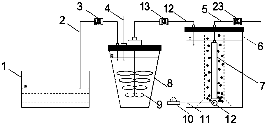
[0034] 10 L of the same sludge as the comparative example was used as the sample injection matrix (the total solid content was 21-22 g / L, and the volatile solid content was 14-15 g / L) into the pretreatment reaction tank 8 continuously, and at the same time gram of dry mud plus 0.015 gram of Fe 2+ Add ferrous sulfate heptahydrate and add 0.043 grams of S per gram of dry mud 2 o 8 2- Potassium persulfate is added, the stirring time (residence time) is set to 2 minutes, and the stirring speed is set to 300 rpm. Subsequently, the treated sludge is continuously injected into the membrane bioreactor 6 through the reactor peristaltic pump 13, and then continuously discharged from the system through the outlet peristaltic pump 23 from the outlet of the flat membrane 7 inside the reactor. Adjust the pump speed of the water outlet peristaltic pump 23 to control the water outlet flow rate at 22 mL / s / m 2 . The aeration rate was set at 5 L / min, and the aeration was continued during th...

Embodiment 2

[0036] 10 L of the same sludge as the comparative example was used as the sample injection matrix (the total solid content was 21-22 g / L, and the volatile solid content was 14-15 g / L) into the pretreatment reaction tank 8 continuously, and at the same time gram of dry mud plus 0.031 gram of Fe 2+ Add ferrous sulfate heptahydrate and add 0.086 grams of S per gram of dry mud 2 o 8 2- Potassium persulfate is added, the stirring time (residence time) is set to 2 minutes, and the stirring speed is set to 300 rpm. Subsequently, the treated sludge is continuously injected into the membrane bioreactor 6 through the reactor peristaltic pump 13, and then the water is continuously discharged from the outlet of the flat membrane 7 inside the reactor through the outlet peristaltic pump 23. Adjust the pump speed of the water outlet peristaltic pump 23 to control the water outlet flow rate at 22 mL / s / m 2 . The aeration rate was set at 5 L / min, and the aeration was continued during the r...

Embodiment 3

[0038] 10 L of the same sludge as the comparative example was used as the sample injection matrix (the total solid content was 21-22 g / L, and the volatile solid content was 14-15 g / L) into the pretreatment reaction tank 8 continuously, and at the same time gram of dry mud plus 0.046 gram of Fe 2+ Add ferrous sulfate heptahydrate and add 0.129 grams of S per gram of dry mud 2 o 8 2- Potassium persulfate is added, the stirring time (residence time) is set to 2 minutes, and the stirring speed is set to 300 rpm. Subsequently, the treated sludge is continuously injected into the membrane bioreactor 6 through the reactor peristaltic pump 13, and then the water is continuously discharged from the outlet of the flat membrane 7 inside the reactor through the outlet peristaltic pump 23. Adjust the pump speed of the water outlet peristaltic pump 23 to control the water outlet flow rate at 22 mL / s / m 2 . The aeration rate was set at 5 L / min, and the aeration was continued during the r...


PUM


Abstract

The invention discloses a synchronous sludge treatment system of a membrane bioreactor and a sludge treatment method thereof. The synchronous sludge treatment system is characterized by consisting ofa reaction tank and a membrane-bioreactor, wherein the membrane-bioreactor is internally provided with a flat sheet membrane; an aeration tube which is connected with an aeration pump is arranged below the membrane-bioreactor. The sludge treatment method of the synchronous sludge treatment system comprises the following steps: pretreating sludge, carrying out membrane biological reactions, and thelike. Compared with the prior art, the membrane pollution velocity is remarkably reduced, COD (Chemical Oxygen Demand) can be removed while the membrane pollution velocity is reduced, the effluent quality is greatly improved, the burden of treatment can be further reduced, the membrane cleaning times and cost can be reduced, the process is simple, the chemical price is low, and a good applicationspace is provided for a later membrane-bioreactor process.

Description

technical field [0001] The invention relates to the field of membrane bioreactor and membrane separation technology, in particular to a treatment system and a treatment method for in-situ membrane pollution prevention and control and synchronous sludge concentration of a membrane bioreactor. [0002] Background technique: [0003] With the improvement of water quality requirements for effluent and reuse, membrane bioreactors are becoming more and more common in practical engineering applications. Membrane Bio-Reactor (Membrane Bio-Reactor) is a wastewater treatment system that organically combines membrane separation technology and biological treatment technology. Membrane Bio-Reactor has high treatment efficiency, good effluent quality, easy automatic control, and simple operation and management. After more than 20 years of development, membrane bioreactor has become one of the main technologies for advanced wastewater treatment. However, the problem of membrane fouling has ...

Claims


Application Information

Patent Timeline
IPC IPC(8): C02F9/14
CPCC02F1/72C02F3/1268C02F2303/14
Inventor 甄广印王建辉陆雪琴潘阳谭宇杰
Owner EAST CHINA NORMAL UNIV
Why Eureka
Try Eureka