Ammonia-containing waste gas ultralow nitrogen emission treatment method and system

A processing system, ultra-low nitrogen technology, applied in separation methods, chemical instruments and methods, and dispersed particle separation, etc., can solve the problems of biodegradation being easily affected by the environment, affecting degradation, and high cost, and achieving the benefits of the overall layout of the system, Good treatment effect and small footprint

Pending Publication Date: 2019-08-13
UNIV OF SCI & TECH LIAONING
View PDF6 Cites 2 Cited by
  • Summary
  • Abstract
  • Description
  • Claims
  • Application Information

AI Technical Summary

Problems solved by technology

[0004] The traditional methods to deal with ammonia mainly include biological method, physical method and chemical method. All three methods are applied in industry. Ammonia waste gas is often a multi-component waste gas. Components other than ammonia may inhibit the metabolic activities of microorganisms, thereby affecting degradation. For example, the component that has the greatest impact on the degradation of ammonia is oxygen, because the bacteria that degrade ammonia are Anaerobic bacteria, so the biological treatment of oxygen-containing ammonia waste gas has great limitations
The physical method is mainly divided into absorption method and adsorption method. The absorption method utilizes the characteristics of ammonia as an alkaline gas and is easily soluble in water, and uses acid liquid to absorb and ne

Method used


Image

  • Ammonia-containing waste gas ultralow nitrogen emission treatment method and system
  • Ammonia-containing waste gas ultralow nitrogen emission treatment method and system
  • Ammonia-containing waste gas ultralow nitrogen emission treatment method and system

Examples


Embodiment Construction

[0024] The specific embodiment of the present invention will be further described below in conjunction with accompanying drawing:

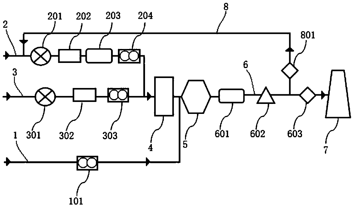
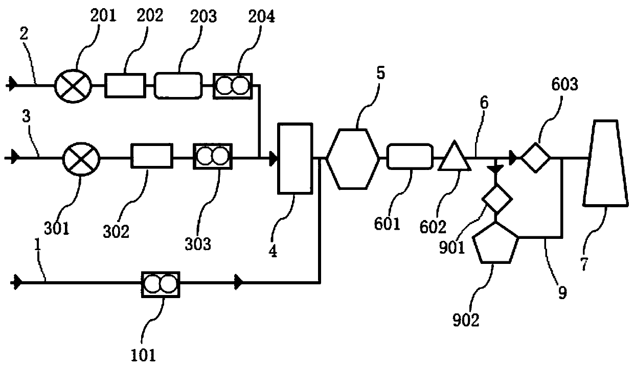
[0025] Such as Figure 1-Figure 3 As shown, a method for treating ammonia-containing waste gas with ultra-low nitrogen emissions described in the present invention comprises the following steps:

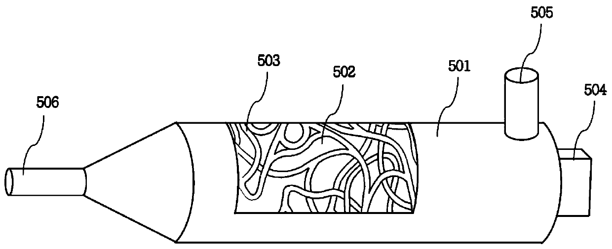
[0026] 1) The complex labyrinth channel reactor 5 is heated by the burner 504, such as image 3 As shown, the reactor body 501 of the complex labyrinth channel reactor 5 is provided with a regenerator 502, and a labyrinth channel 503 is reserved in the regenerator 502, and the labyrinth channel 503 revolves in the reactor body 501, and its ratio Surface area ≥ 1300m 2 / m 3 ;

[0027] 2) After the ammonia-containing waste gas and the oxygen-containing gas are mixed, they are passed into the complex labyrinth channel reactor 5 that has been heated to 900°C-1100°C, and the volume content of the ammonia gas in the mixed gas is kept at 2%-3%. The volume ...


PUM


Abstract

The invention relates to an ammonia-containing waste gas ultralow nitrogen emission treatment method and system. The system comprises an ammonia-containing waste gas conveying pipeline, an oxygen-containing gas conveying pipeline, a combustible gas conveying pipeline, a premixing chamber, a complex maze channel reactor, a tail gas conveying pipeline and a chimney; the combustible gas conveying pipeline is connected with a burner arranged on the complex maze channel reactor; the ammonia-containing waste gas conveying pipeline and the oxygen-containing gas conveying pipeline are connected with an inlet of the premixing chamber separately, an outlet of the premixing chamber is connected with a mixed gas inlet of the complex maze channel reactor, and a tail gas outlet of the complex maze channel reactor is connected with the chimney through the tail gas conveying pipeline. The ammonia-containing waste gas ultralow nitrogen emission treatment method and system have the advantages that the complex maze channel reactor is utilized to achieve a local concentration surface reaction of low-concentration ammonia gas and a coupling interactive oxidation reaction of various organic substances,multi-stage reduction and transformation of nitrogen oxides are also achieved, and finally, ultralow nitrogen pollutant emission of ammonia-containing organic waste gas is achieved.

Description

technical field [0001] The invention relates to the technical field of industrial waste gas purification and treatment, in particular to a method and system for treating ammonia-containing waste gas with ultra-low nitrogen emissions. Background technique [0002] Ammonia (NH 3 ) as a malodorous gas has been included in the discharge standard of odor pollutants in my country, which can cause great harm to the human body and the environment, and is an important source of direct PM2.5. Ammonia and SO 2 , NOx and VOCs react to form aerosol particles, floating in the air will reduce the visibility of the air, falling in the soil will acidify the soil, sinking in the lake will make the lake nutrient, the main component of these aerosol particles is (NH 4 ) 2 SO 4 and NH 4 NO 3 . It can be said that ammonia is the "catalyst" that promotes the formation of PM2.5. [0003] At present, many industries (such as thermal power industry) are widely using the ammonia denitrification...

Claims


Application Information

Patent Timeline
IPC IPC(8): B01D53/76B01D53/58B01D53/86B01D53/56
CPCB01D53/76B01D53/58B01D53/8625
Inventor 李先春苏嘉明李月慧刘玥君李伯阳
Owner UNIV OF SCI & TECH LIAONING
Why Eureka
Try Eureka