
Treatment device and method for incineration gas of cremator

A technology of incineration flue gas and treatment device, which is applied in the field of treatment device for cremation machine incineration flue gas, and can solve problems such as low chimney height, dust removal treatment, and human health hazards in the surrounding environment

Pending Publication Date: 2019-08-30
ZHEJIANG DOWAY ADVANCED TECH CO LTD
View PDF0 Cites 6 Cited by
  • Summary
  • Abstract
  • Description
  • Claims
  • Application Information

AI Technical Summary

Problems solved by technology

[0002] At present, the cremation machines commonly used in crematoriums in my country are fuel oil cremation machines. During the combustion process, toxic air pollutants such as stench, particulate matter, sulfur dioxide, nitrogen oxides, carbon monoxide, and dioxins will be produced. At the same time, chimneys in the funeral industry The altitude is generally low, which leads to the diffusion of air pollutants near the ground, thus causing harm to the surrounding environment and human health
Therefore, in order to reduce the air pollution and other hazards caused by the incineration flue gas of the cremation machine, it is necessary to install a treatment device to treat the flue gas from the cremation machine, but the existing processing device cannot denitrify the flue gas from the spark machine incineration. , desulfurization, dioxin removal and dust removal treatment

Method used


Image

  • Treatment device and method for incineration gas of cremator
  • Treatment device and method for incineration gas of cremator
  • Treatment device and method for incineration gas of cremator

Examples


Embodiment 1

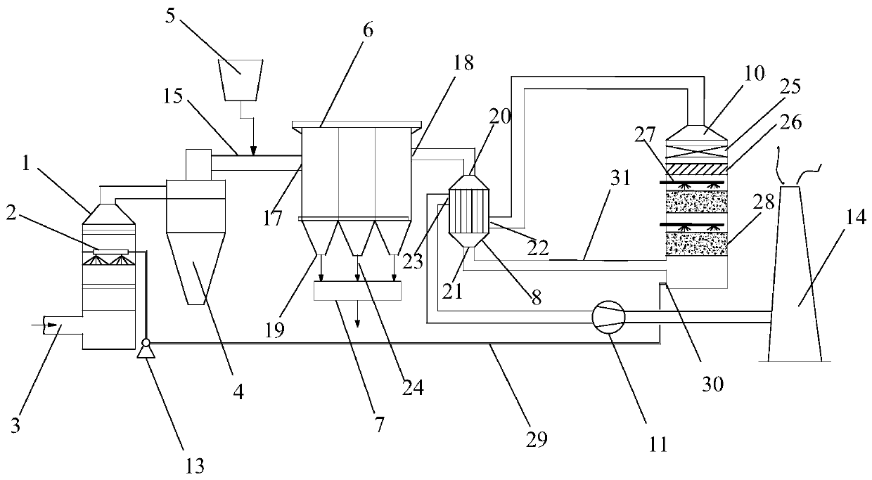
[0046] Please refer to figure 1 Shown: the present invention provides a treatment device for incineration flue gas of cremation machine,

[0047] A treatment device for flue gas incinerated by a cremator, comprising:

[0048] Quenching tower 1 has an inlet and an outlet (not shown in the figure), and the inlet 3 of the quenching tower is used to receive the flue gas after the incineration of the cremator;

[0049] The spark interceptor 4 has an inlet and an outlet (not shown in the figure), and the entrance of the spark interceptor 4 communicates with the outlet of the quench tower 1 through the flue, and the spark interceptor 4 is used for trapping the smoke processed by the quench tower 1 Combustion in the air;

[0050] The bag dust collector 6 has a flue gas inlet 17, a flue gas outlet 18, and an ash outlet 19. The flue gas inlet 17 communicates with the outlet of the Mars interceptor 4 through a straight flue 15; An activated carbon injection device 5 is arranged betwee...

Embodiment 2

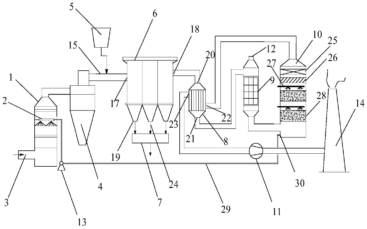
[0068] Such as figure 2 As shown, compared with Embodiment 1, the treatment device for the incineration flue gas of the cremation machine also includes a low-temperature plasma reaction device 9, which is arranged between the heat exchanger 8 and the absorption device 10, and the low-temperature plasma reaction device 9 has Inlet and outlet (not shown in the figure), the inlet of the low-temperature plasma reaction device 9 communicates with the hot gas outlet 21 of the heat exchanger through the flue; The pollutants in the flue gas treated by the heat generator undergo redox reactions.

[0069]In other embodiments, the low-temperature plasma reaction device can be replaced by an ozone generator, and the ozone generator has an inlet and an outlet, and the inlet of the ozone generator is connected with the gas outlet of the oxygen cylinder through a connecting pipe; the ozone generator The outlet of the main flue communicates with the main flue 31 through the flue, and is use...

Embodiment 3

[0105] Take the flue gas incineration of a cremation machine in a funeral home as the implementation, the flue gas value is the flue gas parameter after the quench tower, and the flue gas volume is 5000m 3 / h, oxygen content 14-18%, moisture content 15-20%, odor concentration 5600, SO 2 Average concentration 60mg / Nm 3 , NO x Average concentration 120mg / Nm 3 , the average value of smoke and dust is 160mg / Nm 3 , average value of dioxin 2.0ng TEQ / Nm 3 , the temperature of the flue gas is 172°C, and it is processed by the above-mentioned cremator incineration flue gas treatment device, wherein the operating frequency and operating voltage of the plasma power supply in the low-temperature plasma reaction device are both zero.

[0106] The specific processing steps are as follows: the flue gas incinerated by the above-mentioned cremation machine is transported from the inlet to the quenching tower, and the liquid is sprayed to the flue gas in the tower through the quenching spra...


PUM


Abstract

The invention discloses a treatment device and method for incineration gas of a cremator. The method comprises the following steps: conveying the incineration gas of the cremator to a quenching towerfor treatment, quickly reducing the gas temperature and inhibiting low-temperature synthesis of dioxin; introducing the gas into a Mars interceptor to capture combustibles in the gas; mixing the gas with activated carbon to remove dioxin and heavy metals in the gas; introducing the treated gas into a bag dust collector to capture particles and activated carbon mixed in the gas; introducing the treated gas into a heat exchanger for heat exchange; introducing the treated gas into a low-temperature plasma reaction device for generating active particles required for denitration and desulfurization; introducing the gas into an absorption device to capture acidic substances and residual toxic substances in the gas; introducing the purified gas into the heat exchanger and discharging the purifiedgas after heating treatment. Deep purification of the gas with complex composition and more pollutants including malodorous gas, sulfide, nitrogen oxide and dioxin can be realized, and ultra-low emission of the gas is realized.

Description

technical field [0001] The invention relates to the technical field of flue gas treatment, in particular to a treatment device and method for flue gas incinerated by a cremator. Background technique [0002] At present, the cremation machines commonly used in crematoriums in my country are fuel oil cremation machines. During the combustion process, toxic air pollutants such as stench, particulate matter, sulfur dioxide, nitrogen oxides, carbon monoxide, and dioxins will be produced. At the same time, chimneys in the funeral industry The altitude is generally low, which leads to the spread of air pollutants near the ground, thus causing harm to the surrounding environment and human health. Therefore, in order to reduce the air pollution and other hazards caused by the incineration flue gas of the cremation machine, it is necessary to install a treatment device to treat the flue gas from the cremation machine, but the existing processing device cannot denitrify the flue gas fro...

Claims


Application Information

Patent Timeline
IPC IPC(8): B01D53/75B01D53/78B01D53/70B01D53/56B01D53/50B01D53/48B01D53/32B01D53/06B01D50/00B01D46/02F23J15/02F23J15/04F23J15/06
CPCB01D53/75B01D53/78B01D46/02B01D46/023B01D53/06B01D53/323B01D53/56B01D53/50B01D53/502B01D53/48B01D53/70B01D50/00F23J15/06F23J15/006F23J15/02F23J15/04F23J15/025F23J15/022B01D2258/0283B01D2253/102B01D2257/2064B01D2257/404B01D2259/818F23J2217/10F23J2215/10F23J2215/20F23J2215/301Y02E20/30
Inventor 翁林钢施小东汤宣林叶青戚科技聂菊桃
Owner ZHEJIANG DOWAY ADVANCED TECH CO LTD
Learn More