Annular laser gyro for unmanned navigation chip

A ring laser gyro and unmanned driving technology, which is applied in the field of laser gyroscopes, can solve the problems of affecting the stability of gyroscope performance, the difficulty of gyroscope resonant cavity, and the large loss of integrated optical waveguide, so as to improve the sensitivity of gyroscope, improve the clarity, Effect of Sensitivity Improvement

Inactive Publication Date: 2019-08-30
南京博内特信息科技有限公司
View PDF6 Cites 7 Cited by
  • Summary
  • Abstract
  • Description
  • Claims
  • Application Information

AI Technical Summary

Problems solved by technology

Because there is no high-speed rotor, it is solid and reliable, shock-resistant and vibration-resistant, and has good anti-acceleration performance. The resonant optical gyroscope is one of the important development directions in the field of gyroscopes. It has the advantages of anti-electromagnetic interference and high sensitivity, and has a wide range of applications in high-precision inertial guidance systems. The application prospect of the optical resonator is the core component of the resonant optical gyroscope, and its performance directly determines the accuracy and stability of the gyroscope. The resonator has the advantages of low loss and high definition, but the non-solid-state characteristics seriously affect the stability of the gyroscope performance, and there is polarization noise. The integrated optical waveguide resonator has the advantages of miniaturization, all-solid-state and low cost, and is favored by It is considered to be one of the key development directions of the new generation of high-performance gyroscopes, but the loss of the integrated optical waveguide is large, which seriously limits the improvement of the sensitivity of the integrated optical waveguide resonator gyroscope, and there is polarization noise. In order to reduce the polarization noise, peripheral The polarization controller ensures the single polarization transmission of the optical signal in the gyro transmission optical path, but this severely limits the miniaturization of the gyro system, and the ring resonator will produce errors due to the processing of each reflecting surface, the processing error of the resonator cavity, and the There are errors in the lateral angle deformation of the resonator, etc., which will cause non-coplanar errors in the ring-shaped closed optical path of the resonator. It is difficult to achieve tuning of the gyro resonator, and the preparation process is complicated. The optical resonant cavity is an important direction to be developed in the field of resonant optical gyroscopes

Method used


Image

  • Annular laser gyro for unmanned navigation chip
  • Annular laser gyro for unmanned navigation chip

Examples


Embodiment Construction

[0017] The technical solutions of the present invention will be described in detail below, but the protection scope of the present invention is not limited to the embodiments.

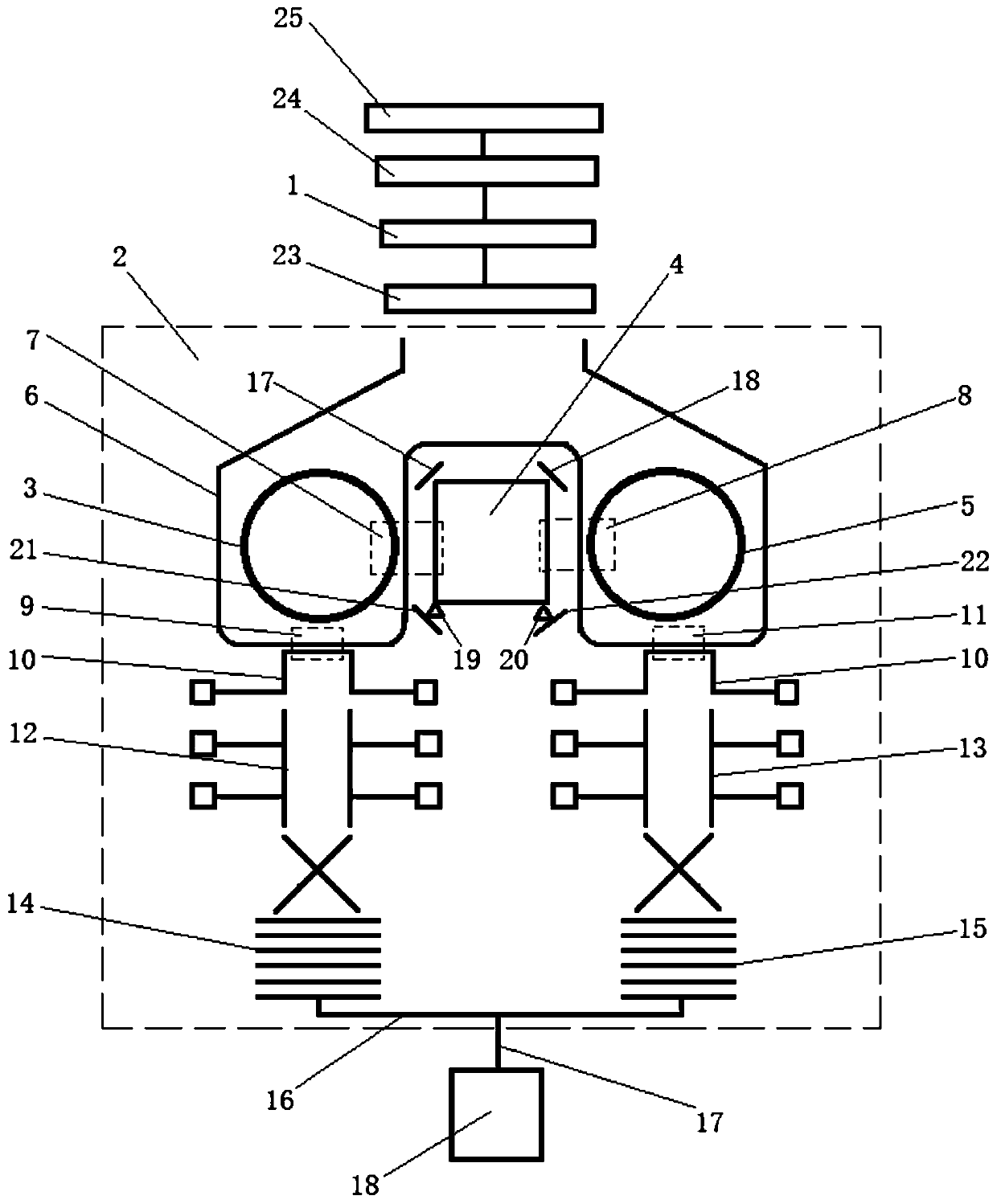
[0018] Such as Figures 1 to 2 As shown, a ring laser gyroscope for unmanned navigation chips of the present invention is characterized in that it includes a pump light source 1 and a gyro chip 2 of an exciter resonator, and the gyroscope chip 2 of the exciter resonator includes an exciter The meta-resonator, the exciter resonator is provided with a first resonant cavity 3, a second resonant cavity 4, a third resonant cavity 5, a gain medium and a connecting fiber 6, and the connecting fiber 6 is connected with the first resonating cavity 3, the second resonating cavity The resonant cavity 4 and the third resonant cavity 5 respectively constitute a self-interference noise reduction resonant cavity, a first coupler 7 is arranged between the first resonant cavity 3 and the second resonant cavity 4, and t...


PUM

PropertyMeasurementUnit
Radiusaaaaaaaaaa
Grating constantaaaaaaaaaa

Abstract

The invention discloses an annular laser gyro for an unmanned navigation chip. The annular laser gyro comprises a pumping light source and a gyro chip of an excimer resonant cavity, wherein the gyro chip of the excimer resonant cavity comprises the excimer resonant cavity, a first resonant cavity, a second resonant cavity, a third resonant cavity, a gain medium and a group connection fiber are arranged in the excimer resonant cavity, the group connection fiber, the first resonant cavity, the second resonant cavity and the third resonant cavity form a self-interference denoising resonant cavity, a first coupler is arranged between the first resonant cavity and the second resonant cavity, and a second coupler is arranged between the second resonant cavity and the third resonant cavity. In the annular laser gyro for the unmanned navigation chip, three parallel resonant cavities form a large resonant cavity system, and the rotation phase difference between clockwise optical interference and counter-clockwise optical interference which are generated by rotation is further improved; and compared with a traditional fiber resonant cavity, the annular laser gyro has more stability, the types and the numbers of components are reduced, and the circuit complexity is simplified.

Description

technical field [0001] The invention relates to a laser gyroscope, in particular to a ring laser gyroscope of a navigation chip. Background technique [0002] Inertial technology is the core technology of inertial navigation, guidance and control, positioning and orientation, attitude stability and overload sensing of various motion carriers in the sea, land, air and space. It has the characteristics of good autonomy, comprehensive information, real-time continuity and strong anti-interference. Carrier motion information perception technology. Inertial technology plays an extremely important role in the field of national defense. The gyroscope is the core device of the inertial system. It is used for the angular motion of the sensitive moving carrier relative to the inertial space, and measures the angular displacement and angular velocity of the carrier, which plays a key role in the performance of the inertial system. Traditional gyroscopes use the orientation and preces...

Claims


Application Information

Patent Timeline
IPC IPC(8): G01C19/72
CPCG01C19/722
Inventor 汪东梅
Owner 南京博内特信息科技有限公司
Why Eureka
Try Eureka