
Transmission type optical fiber nanometer microscope desk based on SPR (Surface Plasma Resonance)

A transmission type, special optical fiber technology, applied in microscopes, optics, optical components, etc., can solve the problems of poor time resolution, low signal-to-noise ratio, and large volume.

Inactive Publication Date: 2019-12-20
GUILIN UNIV OF ELECTRONIC TECH
View PDF7 Cites 1 Cited by
  • Summary
  • Abstract
  • Description
  • Claims
  • Application Information

AI Technical Summary

Problems solved by technology

During evanescent wave microscopy imaging, since the evanescent wave of the excitation field and the surface wave scattered by the sample will interfere with each other, a strong tail will be formed on the side of the sample along the excitation direction, and the length of the tail is equal to the attenuation of the evanescent wave along the surface Long, tailed signals are leaked together with the sample scattering signal and collected by the imaging system, which significantly reduces the imaging signal-to-noise ratio
[0009] 2. Poor spatial resolution
Also due to smearing, when an evanescent wave imaging system images an actual sample with a boundary, streak-like smearing will occur at the boundary, which significantly reduces its resolution
[0010] 3. Poor time resolution
The problem is that it takes a lot of time to obtain a microscopic image, the time resolution is poor, and real-time observation cannot be performed.
[0011] Chinese patent CN 109239020 A proposes a surface wave imaging system based on rotating illumination, which eliminates the tailing caused by the surface wave acting on the sample through the galvanometer scanning system, and improves the signal-to-noise ratio and resolution of the surface wave microscopic imaging , but the types of devices used are large and bulky, resulting in cumbersome and inconvenient
Overcome the shortcomings of traditional surface wave imaging microscopes, such as low signal-to-noise ratio, poor temporal and spatial resolution, and high cost

Method used


Image

  • Transmission type optical fiber nanometer microscope desk based on SPR (Surface Plasma Resonance)
  • Transmission type optical fiber nanometer microscope desk based on SPR (Surface Plasma Resonance)
  • Transmission type optical fiber nanometer microscope desk based on SPR (Surface Plasma Resonance)

Examples


Embodiment 1

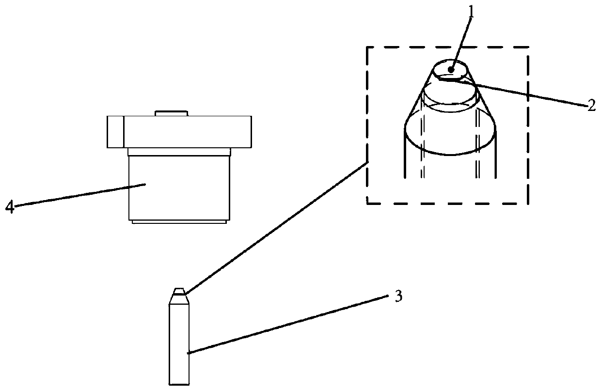
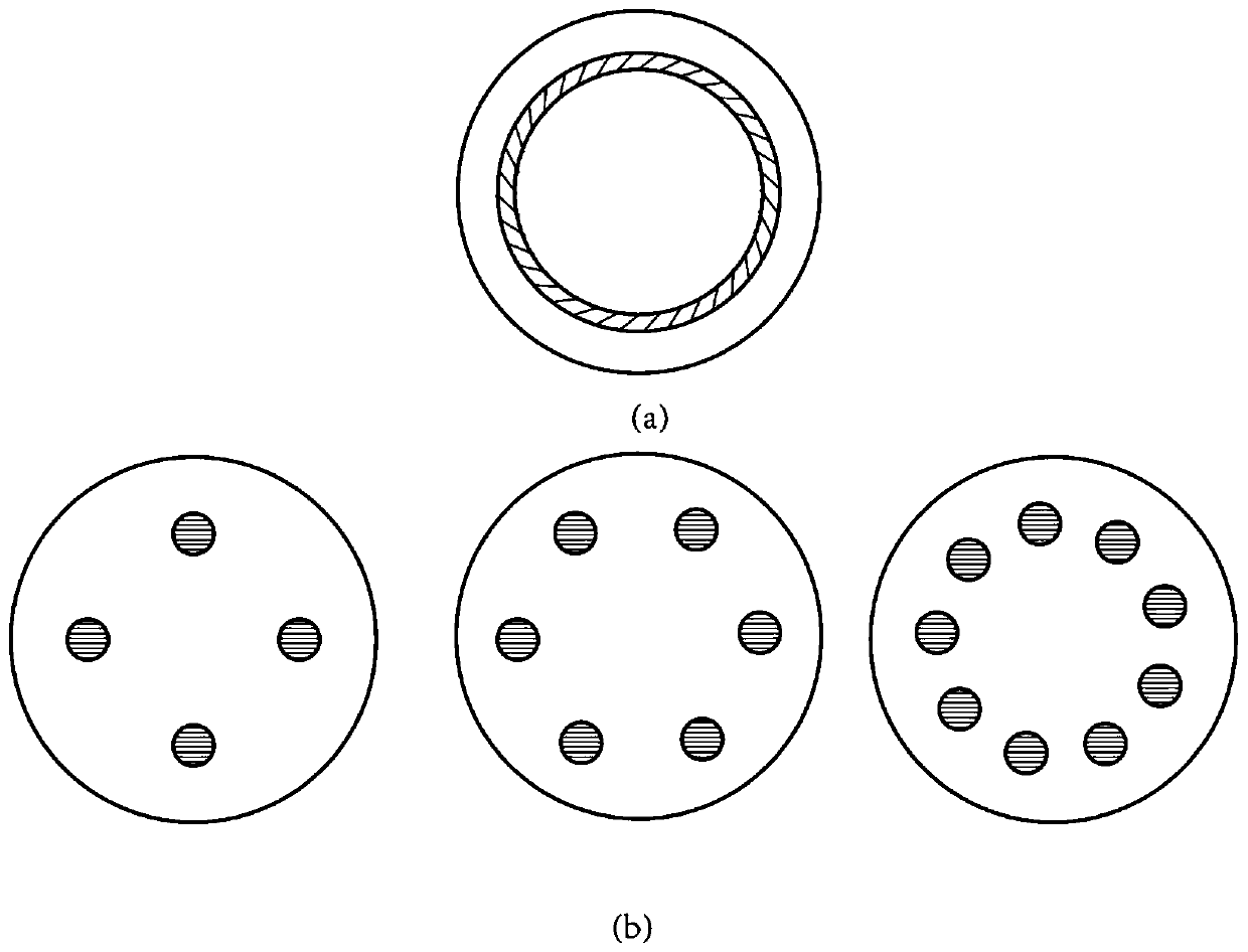
[0034] Image 6 It is a structural schematic diagram of an SPR-based transmission ring-core fiber nanometer microscope according to the present invention. Among them, the end face structure diagram of special optical fiber 3 is as follows image 3 (a) shown.

[0035] Image 6 It is a structural schematic diagram of a transmission-type ring-core fiber nano-microscope based on SPR according to the present invention. Among them, the end face structure diagram of special optical fiber 3 is as follows image 3 shown.

[0036] The description of this embodiment is made using a ring core fiber. Firstly, the metal layer 2 is made, and we coat the surface of the special optical fiber 3 with a 45nm silver film. We place the object to be measured in water or a specific liquid, thereby ensuring that the refractive index of the environment is fixed. From the known parameters of the plasma chip, the refractive index of the prism n 0 =1.56, silver film dielectric constant e 2 =-13.4+1...

Embodiment 2

[0040] Example 2: Figure 7 It is a structural schematic diagram of a transmission ring array multi-core fiber nanometer microscope based on SPR according to the present invention. Among them, the end face structure diagram of special optical fiber 3 is as follows image 3 shown.

[0041] Figure 7 It is a structural schematic diagram of an SPR-based transmissive annular array multi-core fiber nano-microscope according to the present invention. Among them, the end face structure diagram of special optical fiber 3 is as follows image 3 (b) shown.

[0042] The description of this embodiment is carried out by adopting a circular array multi-core optical fiber. Firstly, the metal layer 2 is made, and we coat the surface of the special optical fiber 3 with a 45nm silver film. We place the object to be measured in water or a specific liquid, thereby ensuring that the refractive index of the environment is fixed. From the known parameters of the plasma chip, the refractive inde...


PUM

PropertyMeasurementUnit
Dielectric constantaaaaaaaaaa

Abstract

The invention provides a transmission type optical fiber nanometer microscope desk based on SPR (Surface Plasma Resonance). The transmission type optical fiber nanometer microscope desk based on SPR is characterized by consisting of a special optical fiber 3 and a camera 4, wherein an object 1 to be tested is put onto a metal layer 2; and the special optical fiber 3 is provided with a cone frustum. The surface plasmon resonance can be effectively restrained on the surface of the metal layer 2; in addition, the sensitivity on the environment change is very high; by using the special optical fiber 3 with the cone frustum, surface plasmons are excited by laser to realize the mutual action with a sample; and trailing caused after the surface plasmons act on the sample is eliminated. The transmission type optical fiber nanometer microscope desk based on SPR has the advantages that the special optical fiber is used; the cost can be effectively reduced; the structure can be effectively optimized; the transmission type optical fiber nanometer microscope desk based on SPR can be used for micro-nano microimaging; and images with high signal-to-noise ratio and high-resolution ratio can be obtained.

Description

[0001] (1) Technical field [0002] The invention relates to an SPR-based transmission-type optical fiber nano-microscope table, which belongs to the field of microscopic imaging. [0003] (2) Background technology [0004] The optical microscope is the most commonly used and most effective tool in scientific research optical inspection. When using a conventional microscope, the smallest distance between two objects that can be clearly resolved depends on the limits of the microscope. In order to better observe the microscopic world, researchers are devoting themselves to developing various methods to improve resolution. Super-resolution imaging technology has also continuously made breakthroughs, typical representatives include Confocal Microscope (Confocal Microscope), Stimulated Emission Depletion Microscopy (STED), Photo Activation Localization Microscopy (PALM), etc. . It is worth noting that in all the super-resolution imaging techniques here, the optical path used is ...

Claims


Application Information

Patent Timeline
IPC IPC(8): G01N21/84G01N21/01G01N21/552G02B21/00G02B21/36
CPCG01N21/84G01N21/01G01N21/553G02B21/0092G02B21/0004G02B21/361G01N2021/0112
Inventor 苑立波纪竞凯
Owner GUILIN UNIV OF ELECTRONIC TECH
Learn More