Friction stir and ultrasonic compound welding method of light alloy and resin-based composite

A light alloy, friction stir technology, applied in welding equipment, welding/welding/cutting items, non-electric welding equipment, etc., can solve the problems of changing the microstructure of the base metal, affecting the strength of the joint, reducing the mechanical interlocking ability of the joint, etc. Achieve the effect of increasing temperature and material flow, increasing mechanical interlocking ability, and eliminating the effect of mechanical stirring

Active Publication Date: 2020-01-07
SHENYANG AEROSPACE UNIVERSITY
View PDF15 Cites 12 Cited by
  • Summary
  • Abstract
  • Description
  • Claims
  • Application Information

AI Technical Summary

Problems solved by technology

[0003] When conventional friction stir welding performs lap welding of light alloys and composite materials, the stirring pin penetrates into the lower plate, and the molten composite material will overflow the surface of the weld due to the violent stirring effect. In addition, the effect of violent stirring and heat input can lead to degradation of the composite
Therefore, such defects can be avoided by not piercing the upper plate, but this method reduces the mechanical interlock ability in the joint
[0004] The Chinese invention patent (publication number: CN108857069A, publication date: November 23, 2018) discloses a laser-arc-assisted method for welding composite materials and copper alloys, in which tungsten rods are used to weld the molten pool Stirring, but this process needs to be completed at a higher temperature, too high a temperature will cause severe expansion and degradation of the composite material
[0005] Chinese invention patent (publication number: CN106736030A, publication date: May 31, 2017) discloses a solder and its welding C / SiC composite material and metal, Chinese invention patent (publication number: CN101786898A, publication date: 2010 July 28) disclosed a method for connecting Cf / SiC composite materials and Ni-based superalloys. Both of them use vacuum brazing to connect the joints, but some elements in the brazing filler metals will interact with metal materials. Reaction, produce hard and brittle intermetallic compounds, affect the strength of the joint, and the overall heating will change the microstructure of the base metal
[0006] Chinese invention patent (publication number: CN106113484A, publication date: November 16, 2016) discloses a method for connecting thermoplastic composite materials to metals, which uses electromagnetic induction heating to connect thermoplastic composite materials to metals. The method has the characteristics of simple equipment, but lacks mechanical interlock at the welding interface, and is only suitable for the connection of thermoplastic composite materials
[0007] Chinese invention patent (publication number: CN101774062A, publication date: July 14, 2010) discloses a method of argon arc melting and brazing of laminated composite materials and stainless steel, which needs to be heated to 900°C during this process. The impact of composite materials is greater, and there will be more air hole defects in joints after composite materials are degraded

Method used


Image

  • Friction stir and ultrasonic compound welding method of light alloy and resin-based composite
  • Friction stir and ultrasonic compound welding method of light alloy and resin-based composite

Examples


Embodiment 1

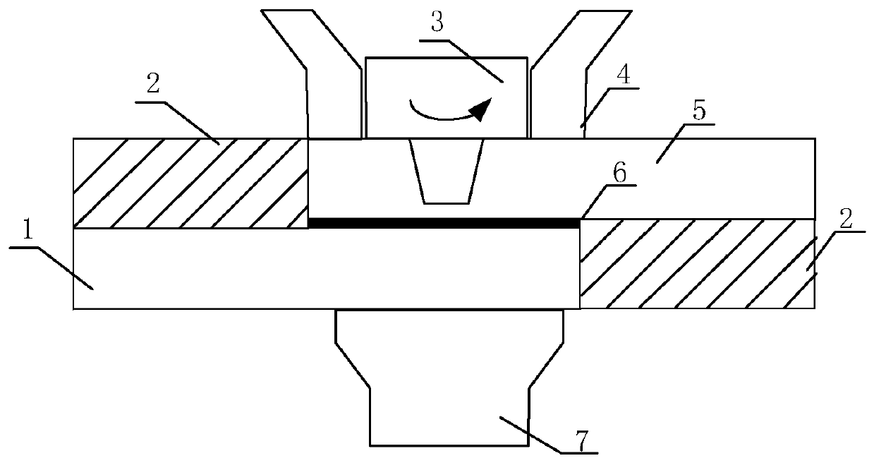
[0034] Such as Figure 1-2 As shown, in this embodiment, the present invention is used to connect the light alloy and the resin-based composite material. The light alloy 5 in this embodiment is 2024 aluminum alloy, and the composite material 1 is a carbon fiber reinforced PEEK composite material, both of which have the same thickness 5mm, the specific steps are as follows:

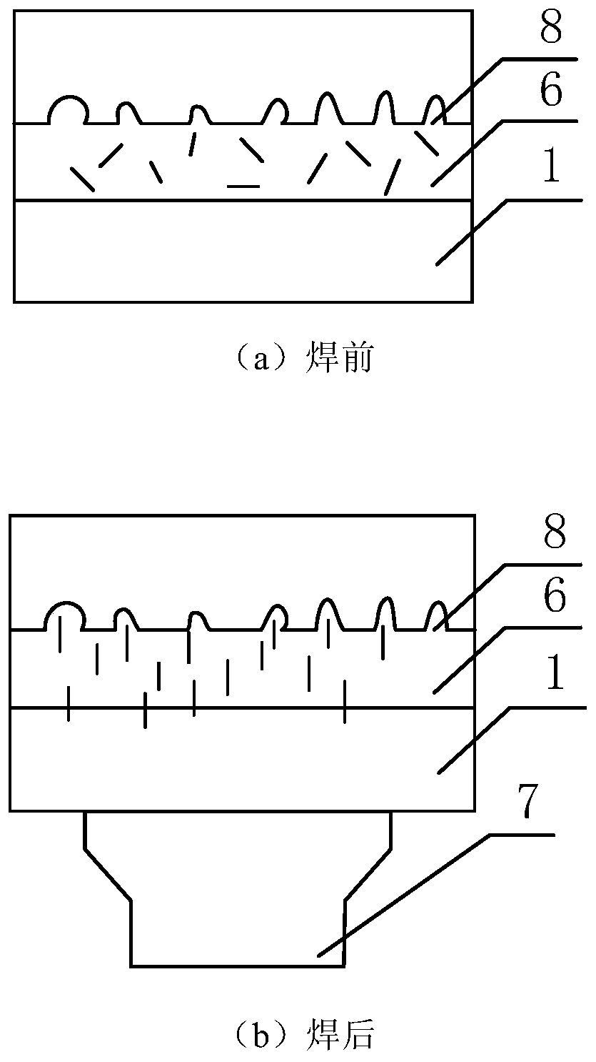
[0035] Step 1: Anodize the surface of the 2024 aluminum alloy in contact with the carbon fiber reinforced PEEK composite material to form a porous layer structure on the surface;

[0036] Step 2: Place the 2024 aluminum alloy as the upper plate and the carbon fiber reinforced PEEK composite material as the lower plate on the workbench. The carbon nanotube composite material film 6 in the middle layer selects a carbon nanotube reinforced PEEK film with a mass fraction of 1%. 0.2mm, with the aid of block 2, fix it with a clamp; choose a suitable external auxiliary heating stationary shoulder 4, and ensure t...

Embodiment 2

[0042] In this embodiment, the present invention is used to connect the light alloy and the resin-based composite material. The light alloy 5 in this embodiment is 2024 aluminum alloy, and the composite material 1 is a carbon fiber reinforced PEEK composite material, both of which have a thickness of 2 mm. Specific steps are as follows:

[0043]Step 1: Texturize the surface of the TC4 titanium alloy that is in contact with the carbon fiber reinforced PEEK composite material to greatly increase the connection area at the interface;

[0044] Step 2: Place the 2024 aluminum alloy as the upper plate and the carbon fiber reinforced PEEK composite material as the lower plate on the workbench. The carbon nanotube composite material film 6 in the middle layer selects a carbon nanotube reinforced PEEK film with a mass fraction of 1%. 1.5mm, with the aid of block 2, fix it with a clamp; choose a suitable external auxiliary heating stationary shoulder 4, and ensure that the distance betw...


PUM

PropertyMeasurementUnit
thicknessaaaaaaaaaa
quality scoreaaaaaaaaaa

Abstract

The invention relates to a friction stir and ultrasonic compound welding method of light alloy and a resin-based composite. The method comprises the steps that firstly, the surface, making contact with the resin-based composite, in the light alloy is subjected to mechanical processing or electrochemical processing; secondly the light alloy serves as an upper plate, the resin-based composite servesa lower plate, a carbon nano tube composite thin film serves as a middle layer, and the upper plate, the lower plate and the middle layer are placed on a worktable and fixed; thirdly, an ultrasonic system is connected; fourthly, a stirring head is rotated and carries out downward pricking; fifthly, the ultrasonic system is started; and sixthly, after the shaft shoulder of the stirring head and the upper plate are in contact, the stirring head stays for 3 to 120 s, and then, the stirring head moves in the welding seam direction at the speed of 5 to 1000 mm/min until welding is finished. The welding seam width can be increased, the microcosmic mechanical interlocking capacity in the joint is increased, and the joint anti-shearing and stretching property can be improved.

Description

technical field [0001] The invention belongs to the technical field of metal and composite material connection, and in particular relates to a friction stir and ultrasonic composite welding method of light alloy and resin-based composite material. Background technique [0002] As a material with good fatigue resistance, good corrosion resistance and good designability, composite materials have been widely used in the manufacture of structural parts such as aircraft wings and front fuselages, large launch vehicle shells and engine shells. The field of lightweight manufacturing plays an important role and responds well to the global demands placed on environmental protection. Lightweight alloys are also widely used in manufacturing fields such as aerospace and ship transportation. Therefore, the connection of lightweight alloys with composite materials is inevitable. In the connection between light alloys and composite materials, the bonding method requires more complicated ...

Claims


Application Information

Patent Timeline
Patent Type & Authority Applications(China)
IPC IPC(8): B23K20/12B23K20/10B23K20/233B23K20/26B23K103/16
CPCB23K20/10B23K20/12B23K20/233B23K20/26B23K2103/172
Inventor 姬书得刘景麟熊需海吕赞马琳张利国胡为龚鹏
Owner SHENYANG AEROSPACE UNIVERSITY
Why Eureka
Try Eureka