

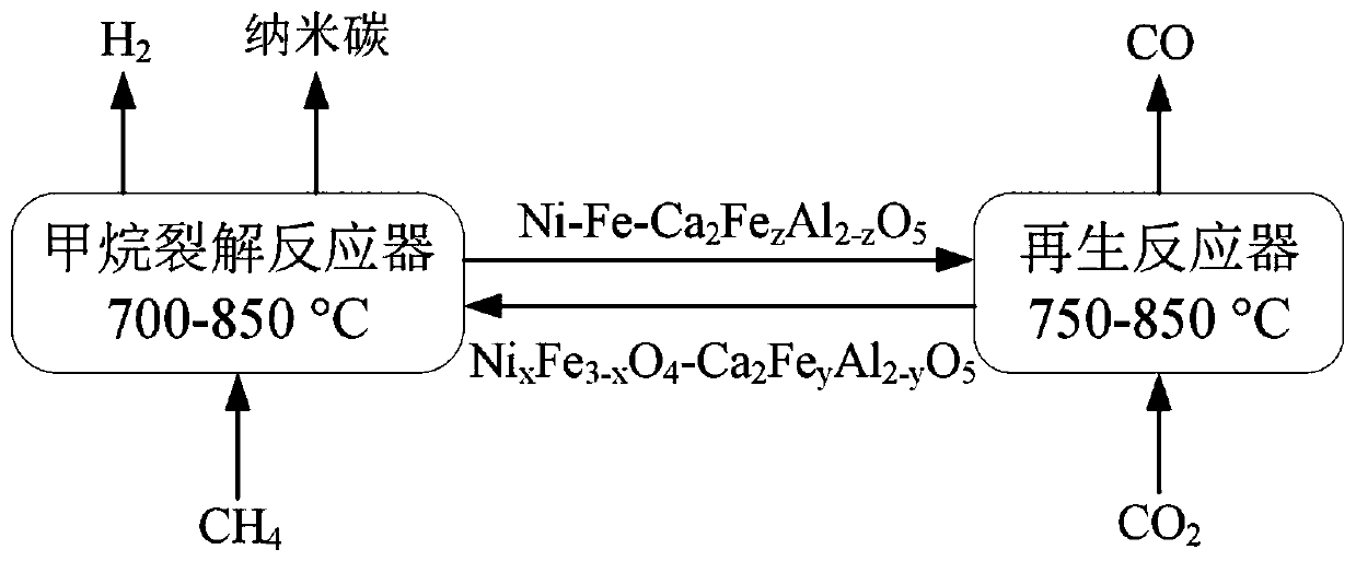
Chemical-looping circulation method for coupling of hydrogen production through methane cracking with CO2 reduction
A chemical chain and methane technology, applied in chemical instruments and methods, inorganic chemistry, carbon monoxide, etc., to achieve the effects of solving carbon deposition problems, efficient conversion, and restoring phases and activities
- Summary
- Abstract
- Description
- Claims
- Application Information
AI Technical Summary
Problems solved by technology
Method used
Image

Examples
Embodiment 1
[0077] 1) Mix iron nitrate, calcium nitrate, nickel nitrate, aluminum nitrate and citric acid (in the material, the molar ratio of Ca-Fe-Al-Ni element is 4:4:1:1), and the molar addition amount of citric acid is all 1.3 times the total molar weight of metal atoms;
[0078] 2) Add deionized water to configure a solution, satisfying that the concentration of nickel nitrate solution in the mixed solution is 0.10mol / L;
[0079] 3) Stir the prepared solution at 40°C for 30 minutes;
[0080] 4) Put the solution obtained in step 3) in a drying oven, foam and dry for 5 hours at a temperature range of 180° C., and crush and grind the obtained solid sample;
[0081] 5) Put the ground sample in step 4) into a muffle furnace, and calcinate it at 850° C. for 4 hours in an air atmosphere. The heating rate is guaranteed to be 2.5° C. / min, and the calcined solid powder is ground to The particle size is less than 0.3mm, and finally NiFe is obtained 2 o 4 -Ca 2 Fe 1.52 Al 0.48 o 5 (mark...
Embodiment 2
[0142] Compared with Example 1, the only difference is that the reaction temperatures in step (1) are respectively 600°C, 650°C, 700°C, 750°C, 800°C or 850°C.
[0143] For methane conversion rate, hydrogen production rate and product content data at different temperatures, see Figure 10-12 .
[0144] After determining the best catalytic oxygen carrier, we optimized the reaction temperature range, taking the hydrogen production rate, hydrogen concentration and methane conversion rate as indicators, the results are as follows Figure 10-Figure 12 shown. It is found that the temperature range of 750-800°C is the optimal temperature range for catalytic methane cracking, and the hydrogen concentration can be as high as about 95%. The high methane conversion rate and high hydrogen concentration solve the separation problem of hydrogen and methane.
Embodiment 3
[0146] Compared with Example 1, the only difference is that the reaction temperatures in step (2) are respectively 750°C, 800°C, 850°C or 900°C.
[0147] Explore the carbon dioxide reduction stage through Example 3, the relationship between CO production rate and CO concentration at different temperatures, the results are as follows Figure 13 to Figure 18 As shown, it can be found that by using CFAN as a catalytic oxygen carrier, we can achieve relatively low temperature and high CO 2 The conversion rate and high CO selectivity have outstanding advantages compared with the existing technology.
PUM
 Abstract
Description
Claims
Application Information