
Synchronous monitoring method for chemical signals and electric signals of neural cell network

A technology of nerve cells and electrical signals, applied in the direction of material electrochemical variables, measuring devices, scientific instruments, etc., to meet the monitoring requirements, low background signal, and have the effect of time-space resolution responsiveness

Active Publication Date: 2020-01-17
NANJING UNIV
View PDF3 Cites 1 Cited by
  • Summary
  • Abstract
  • Description
  • Claims
  • Application Information

AI Technical Summary

Problems solved by technology

However, there is no report on synchronous monitoring of electrical and chemical signals

Method used


Image

  • Synchronous monitoring method for chemical signals and electric signals of neural cell network
  • Synchronous monitoring method for chemical signals and electric signals of neural cell network
  • Synchronous monitoring method for chemical signals and electric signals of neural cell network

Examples


Embodiment 1

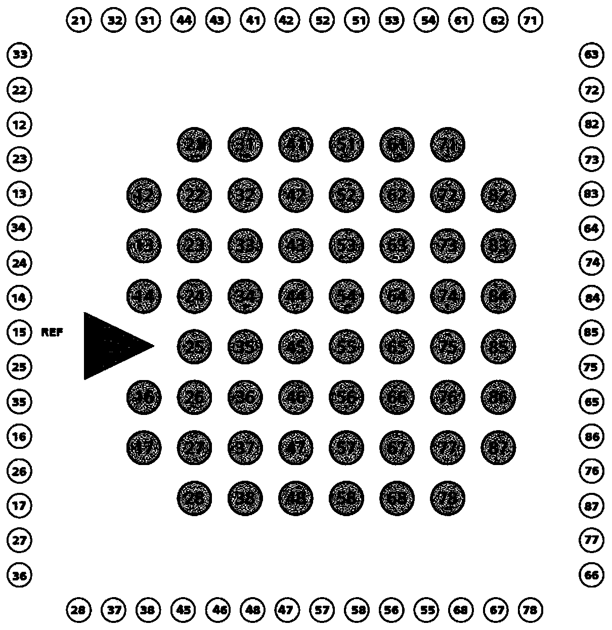
[0033] This embodiment uses an ultra-thin 8×8 microelectrode array with a thickness of 180 μm, the model is 60ThinMEA200 / 30iR-ITO, and the layout is as follows figure 1 shown; figure 1 The middle position shown is the electrode, REF is the reference electrode, surrounded by pins, the first digit of the electrode number is the number of columns, and the second digit is the number of rows; the diameter of a single electrode is 10 μm, the spacing is 30 μm, and the electrode resistance 250 ~ 400kΩ, the electrode material is TiN; the surface of the microelectrode array is provided with a liquid reservoir, the inner diameter is 24mm, and the height is 12mm.

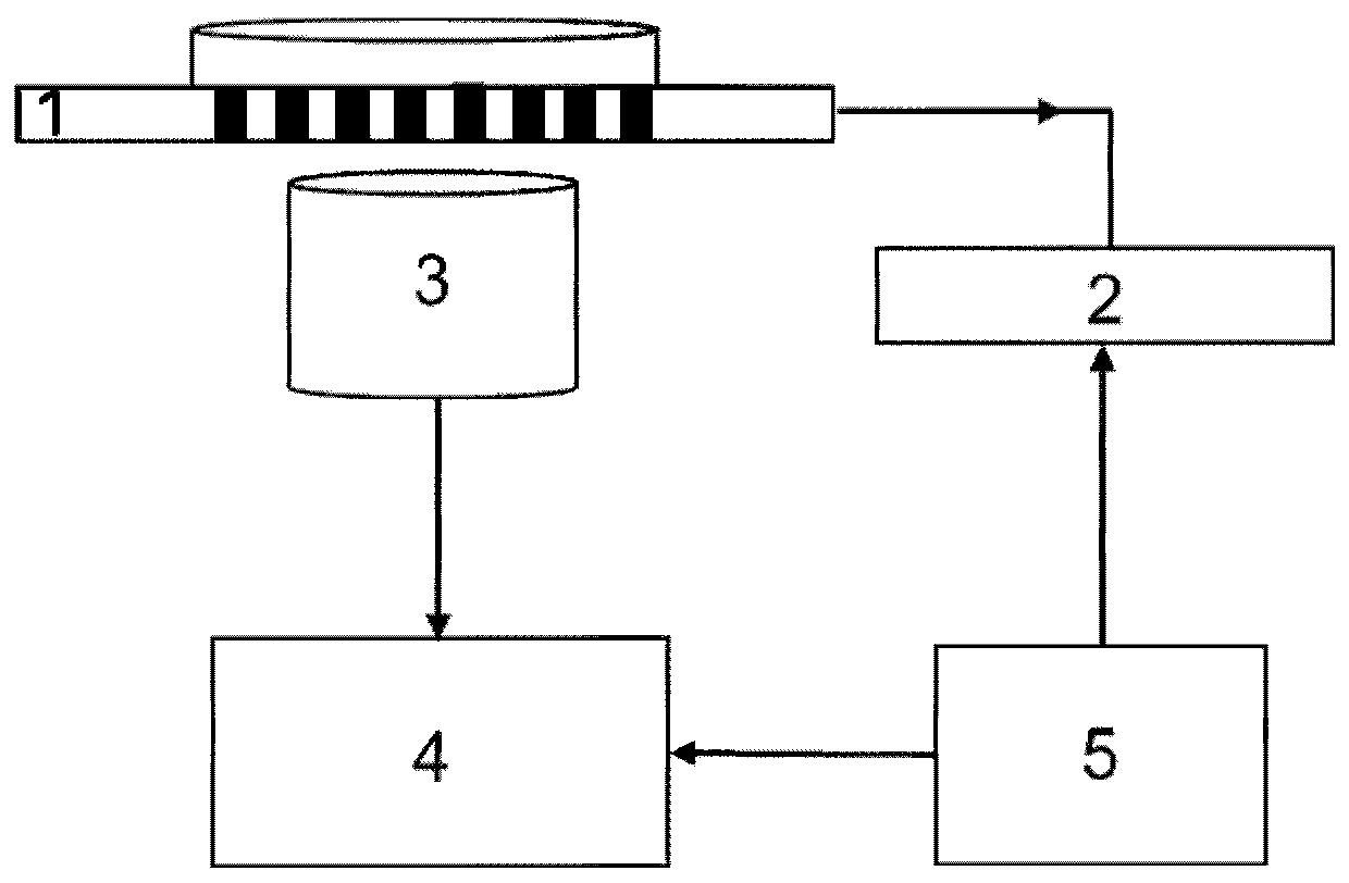
[0034] The detection device of this embodiment is as figure 2 As shown, the microelectrode array 1 is installed on the stage of the total internal reflection fluorescence microscope, so that the microelectrode array 1 is located directly above the total internal reflection objective lens 3; the electrical signal collected by ...

Embodiment 2

[0044] This embodiment adopts the microelectrode array of the same model as that of embodiment 1, and the detection device is the same as that of embodiment 1; the specific steps of using the above microelectrode array in conjunction with a total internal reflection fluorescence microscope device to monitor the chemical signals and electrical signals of the nerve cell network as follows:

[0045] (1) Pretreatment of the microelectrode array: first, the microelectrode array was rinsed in ethanol solution for 20 minutes, then air-dried in the air; finally, 75% ethanol was used for disinfection, and after natural air-drying, it was irradiated with ultraviolet light for 6 hours; Add 0.1 mg / ml polylysine solution to the microelectrode reservoir, and let it stand for 1 hour at 37 ° C in a 5% carbon dioxide environment; then thoroughly clean the microelectrode array with distilled water; finally, use chemical modification method, Put the laminin in the reservoir and let it stand over...


PUM

PropertyMeasurementUnit
Thicknessaaaaaaaaaa
Diameteraaaaaaaaaa
The inside diameter ofaaaaaaaaaa

Abstract

The invention discloses a synchronous monitoring method for chemical signals and electric signals of a neural cell network. The method comprises the following steps of firstly, culturing a neural cellnetwork on a pretreated microelectrode array in situ; then dyeing neuron vesicles, and adding a buffer solution; observing the neural cell network by adopting a total internal reflection fluorescencemicroscope, and connecting a shooting camera and a controller of the microelectrode array with a pulse signal generator; and performing external stimulation on the neural cell network, starting the pulse signal generator, and synchronously collecting fluorescence signals and electric signals by the shooting camera and the controller of the microelectrode array respectively. The synchronous monitoring method is low in background signal and high in signal-to-noise ratio, has space-time resolution responsiveness, and can meet the monitoring requirements of the neural cell network; the method isstable in signal and high in sensitivity, can achieve imaging measurement for various neural cells and networks, and can achieve high-throughput analysis.

Description

technical field [0001] The invention relates to a detection method of nerve cells, in particular to a method for synchronously monitoring chemical signals and electrical signals of nerve cell networks. Background technique [0002] It is far-reaching to explore the structure and information processing mechanism of the nervous system and reveal the nature of high-level neural activities. All advanced functions of the nervous system are inseparable from the generation, transmission, processing and storage of signals. Neuron, also known as nerve cell, is the basic unit that constitutes the structure and function of the nervous system. Its interaction and connection constitute an extremely complex network system, which transmits the behavior of organisms through electrical and chemical signals. The research on the information transmission mechanism between neuron clusters is close to the essence of life existence, has great scientific significance and application value, and is ...

Claims


Application Information

Patent Timeline
IPC IPC(8): G01N21/64G01N27/327G01N27/48
CPCG01N21/6428G01N27/48G01N27/3277
Inventor 徐琮辉赵微崔美荣徐静娟陈洪渊
Owner NANJING UNIV
Learn More