Metal selective melting forming method based on laser spot patterning output

A technology of laser spot and selective melting, which is applied in the field of metal laser processing, can solve the problems of production efficiency, workpiece layer quality, isotropy, and workpiece defects, etc., to avoid anisotropy on the metal workpiece layer, and to avoid Anisotropy, the effect of improving molding efficiency

Active Publication Date: 2020-02-28
INST OF MACHINERY MFG TECH CHINA ACAD OF ENG PHYSICS
View PDF7 Cites 4 Cited by
  • Summary
  • Abstract
  • Description
  • Claims
  • Application Information

AI Technical Summary

Problems solved by technology

The connection between the powder layers of dot-matrix scanning and linear-matrix scanning sintering is too regular, the isotropy is difficult to satisfy, the performance of the part is not easy to guarantee, and it is also prone to product defects; The swing and the field mirror cooperate to complete the scanning task of "from point to line, from line to surface", and the speed is relatively low. At present, the existing powder-spreading metal laser additive manufacturing process is equipped with point scanning or line scanning. The production efficiency and workpiece sheet quality are affected
The traditional point / line scanning method needs to design and plan the scanning direction, scanning path and scanning spacing, etc., resulting in anisotropy on the metal workpiece sheet, although the traditional point-line scanning method adopts corner processing when scanning each slice layer , but there are still some isotropic

Method used


Image

  • Metal selective melting forming method based on laser spot patterning output
  • Metal selective melting forming method based on laser spot patterning output
  • Metal selective melting forming method based on laser spot patterning output

Examples


Embodiment 1

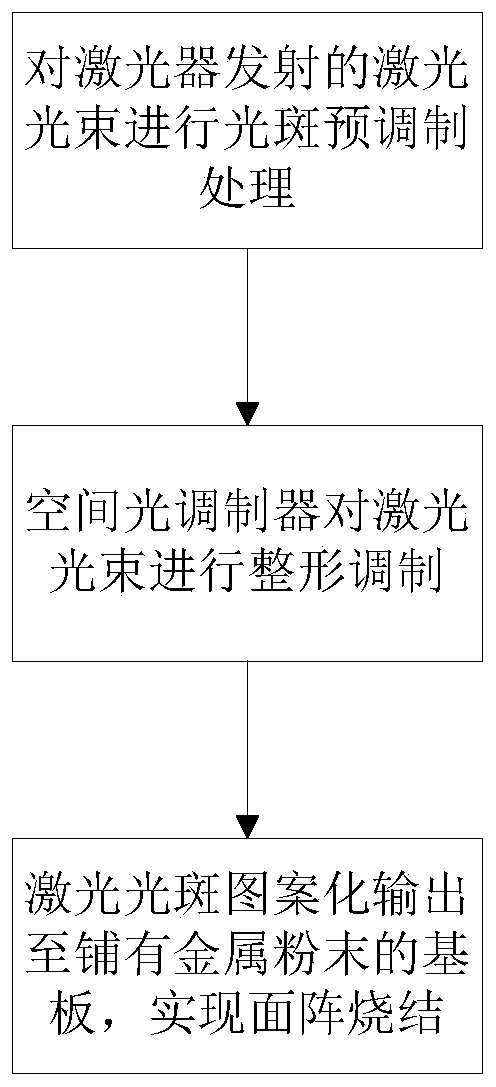
[0039] This embodiment proposes a metal selective melting forming method based on the patterned output of the laser spot, such as figure 1 As shown, the method includes the following steps:

[0040] Step 1: Perform spot pre-modulation on the laser beam to obtain the initial seed light and enter it into the spatial light modulator for processing.

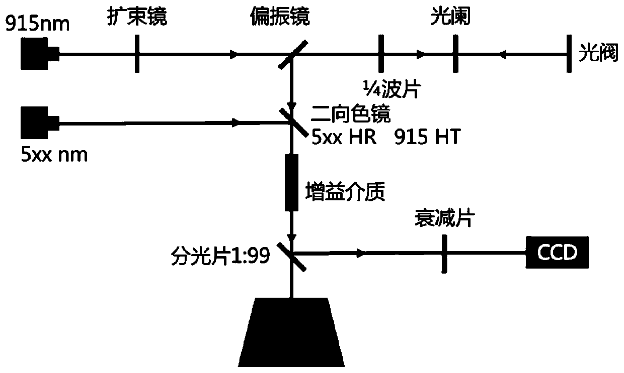
[0041] In this embodiment: First, build as figure 2 The laser light path and equipment platform are shown, and then the terminal light path output is directed to the substrate covered with metal powder, and the beam direction is perpendicular to the substrate. The laser light path and equipment platform in this embodiment specifically include: a laser, a beam expander, a polarizer, a quarter wave plate, an aperture, and a spatial light modulator (the spatial light modulator in this embodiment adopts but is not limited to Light valve); It also includes a substrate covered with metal powder, as well as attenuators and CCDs for measuring op...

Embodiment 2

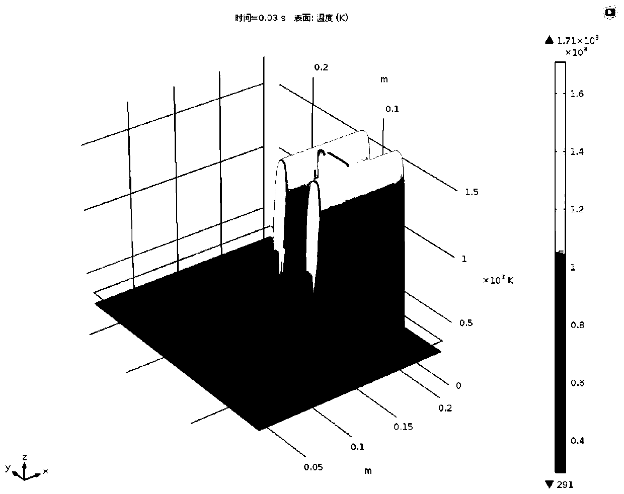
[0057] In this embodiment, the method proposed in the above embodiment 1 is used to simulate the forming temperature field of 6061 material, and obtain the following image 3 The simulation renderings shown are by image 3 It can be seen that when the laser spot is a planar patterned spot, the exposure and sintering of the area to be processed is completed instantaneously. The instantaneous time in the figure is 0.03 seconds, and the highest temperature in the exposed area can reach within 0.03s of exposure time. At 1700K, the highest uniform and stable temperature area is about 1200K. This temperature has reached the melting point of aluminum alloy and can be sintered. The sintering effect (such as under-burning, over-burning, moderate) is determined by the exposure time and exposure power. The effect diagram shows that the temperature field generated by surface exposure is more uniform, avoiding the multiple molten pools generated by point scanning exposure and sintering and ...


PUM


Abstract

The invention discloses a metal selective melting forming method based on laser spot patterning output. The method comprises the steps that firstly, laser beams are subjected to spot pre-modulation, and obtained initial seed light is incident into a spatial light modulator to be processed; secondly, a preprocessed metal model slice is input into a control system of the spatial light modulator, thecontrol system drives the spatial light modulator, and the incident initial seed light is modulated into spot patterning seed light in the shape corresponding to the metal model slice to be output; and thirdly, the spot patterning seed light output by the spatial light modulator is subjected to power amplification, the amplified light beams are projected to a base plate paved with metal powder, and metal powder area array sintering is achieved by adjusting the power density of laser projected to the base plate. According to the metal selective melting forming method, anisotropy on a metal workpiece slice layer due to the fact that path planning is too regular is avoided to the maximum degree, and accordingly the forming quality is improved.

Description

Technical field [0001] The invention relates to the technical field of metal laser processing, and in particular to a method for metal selective melting and forming based on laser spot patterned output. Background technique [0002] At this stage, the more mature technologies in metal laser additive manufacturing are SLM and LMDF, which are point-scanning and line-scanning respectively, which are also called laser dot matrix and linear melting manufacturing technologies. Lattice scanning and linear scanning sintered powder layer connection is too regular, the homogeneity is difficult to satisfy, the performance of the part is not easy to guarantee, and part defects are prone to occur; at the same time, the processing method of dot and line array requires constant galvanometer The swing and the field lens cooperate to complete the scanning task of "from point and line, from line to surface", and the speed is relatively low. The current powder coating metal laser additive manufactu...

Claims


Application Information

Patent Timeline
Patent Type & Authority Applications(China)
IPC IPC(8): B22F3/105B33Y10/00B33Y50/02
CPCB33Y10/00B33Y50/02B22F10/00B22F12/41B22F10/28B22F12/44B22F10/36Y02P10/25
Inventor 沈显峰王晨光王国伟吴鸿飞郭林辉吴华玲
Owner INST OF MACHINERY MFG TECH CHINA ACAD OF ENG PHYSICS
Why Eureka
Try Eureka