Organic electroluminescent compound, preparation method and application thereof

An electroluminescence and compound technology, which is applied in the field of organic electroluminescence compounds and their preparation, can solve the problems of high driving voltage and need to improve current efficiency, and achieves the advantages of improving device efficiency, preventing molecular crystallization of light-emitting layer materials, and improving color purity. Effect

Active Publication Date: 2020-03-06
NINGBO LUMILAN NEW MATERIAL CO LTD
View PDF6 Cites 14 Cited by
  • Summary
  • Abstract
  • Description
  • Claims
  • Application Information

AI Technical Summary

Problems solved by technology

However, the driving voltage of the above-mentioned organic electroluminescent devices is relatively high, and the current efficiency needs to be improved.

Method used

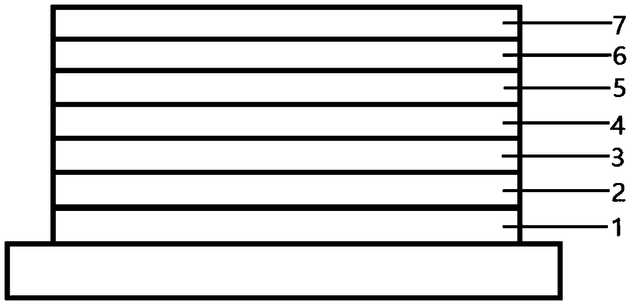

Image

  • Organic electroluminescent compound, preparation method and application thereof
  • Organic electroluminescent compound, preparation method and application thereof
  • Organic electroluminescent compound, preparation method and application thereof

Examples


Synthetic example 1

[0103] This synthesis example provides an intermediate 1 and its synthesis route:

[0104]

[0105] In a 1L three-necked flask at -78°C under nitrogen, add a solution of 2,2,6,6-tetramethylpiperidine (TEMPO, 20mL) in anhydrous tetrahydrofuran (200mL), and add Butyllithium (n-BuLi, 160mmol) tetrahydrofuran solution (80mL), reacted at 0°C for 20 min, put the reaction solution back at -78°C, and added dropwise starting material 1: 2-chloroquinoxaline (16.5g , 100mmol) in tetrahydrofuran (100mL), react at low temperature for 30min, add 200mL concentrated hydrochloric acid and 300mL ethanol dropwise to the reaction solution, and stir for 1h. The reaction solution was extracted with dichloromethane and purified by column chromatography (mixed solvent of petroleum ether PE and ethyl acetate EA) to obtain intermediate 1: 3,3'-dichloro-2,2'-biquinoxaline ( 19.2 g, 59% yield).

[0106] Intermediate 1 was prepared according to the above synthetic route, and the specific structural f...

Synthetic example 2

[0112] This synthesis example provides a raw material And its synthetic route:

[0113]

[0114]In a dry 500mL double-neck round-bottom flask, fill nitrogen, add 2-naphthyl bromide (20.6g, 0.1mol), double pinacol base diboron (25.4g, 0.1mol), potassium acetate (19.6g, 0.2 mol), [1,1'-bis(diphenylphosphino)ferrocene]dichloropalladium(II) (0.005mol), 1,4-dioxane (200mL), react at 120°C for 8h; After the reaction is complete, cool to room temperature, quench with water, extract with dichloromethane (200mL extraction three times), the extract is dried with anhydrous magnesium sulfate, spin-dried, and the crude product is separated by silica gel column chromatography to obtain 2-naphthylboronic acid Nacohol ester (15.5 g, 61% yield).

Synthetic example 3

[0116] The difference between this synthesis example and synthesis example 2 is that 2-naphthyl bromide is used with an equimolar amount of 3-bromo-1,1'-biphenyl Substitute to get 3-biphenylboronic acid pinacol ester (17.9 g, 64% yield).


PUM

PropertyMeasurementUnit
thermal decomposition temperatureaaaaaaaaaa
current efficiencyaaaaaaaaaa
thermal decomposition temperatureaaaaaaaaaa

Abstract

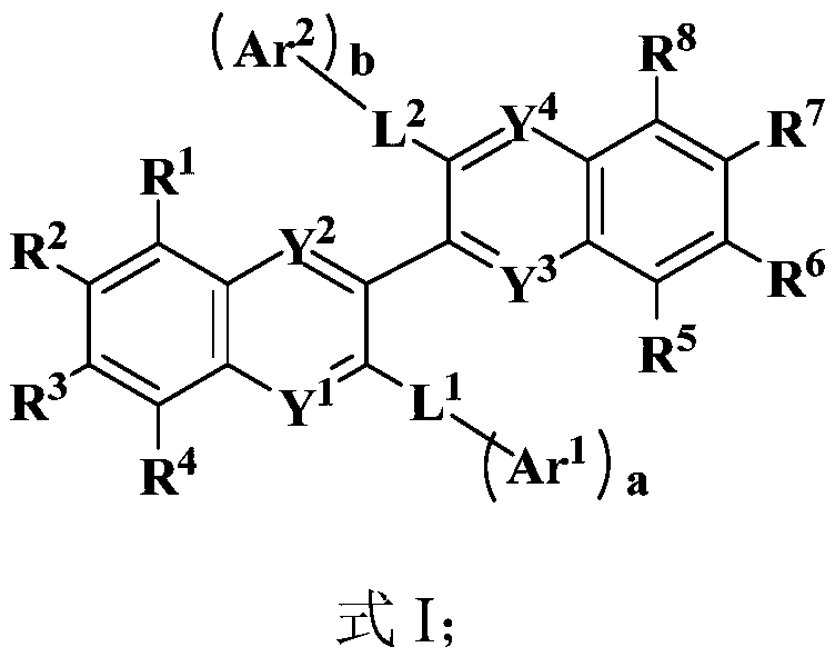
The invention provides an organic electroluminescent compound, a preparation method and application thereof. The organic electroluminescent compound has a structure shown as formula I, is suitable foruse as a luminescent layer host material of an organic electroluminescent device, has double dipolarity, wherein the HOMO energy level and LUMO energy level are respectively positioned on different electron donating groups and electron withdrawing groups, and can match adjacent hole transport layer and electron transport layer, and the charge-hole transport balance is good, thus enlarging the area for compounding holes and electrons into electrons in the luminescent layer, reducing the exciton concentration, preventing triplet state-triplet state annihilation of the device, and improving thedevice efficiency. As a luminescent layer host material, the organic electroluminescent compound makes the area where carriers are compounded far from an adjacent interface of the luminescent layer and the hole or electron transport layer, improves the color purity of an OLED device, and at the same time can prevent excitons from passing back to the transport layer, thus further improving the device efficiency.

Description

technical field [0001] The invention belongs to the technical field of organic electroluminescent materials, and in particular relates to an organic electroluminescent compound and its preparation method and application. Background technique [0002] In 1987, Dr. Deng Qingyun and others from the laboratory of Eastman Kodak made the first organic light-emitting diode (OLED) device (hereinafter referred to as OLED device) by vacuum evaporation for the first time. (Appl.Phys.Lett., 1987,51,913), they used transparent and conductive indium tin oxide (ITO) as the cathode, and sequentially evaporated diamine derivatives and tris (8-hydroxyquinoline) on it ) aluminum, and magnesium-silver alloy is used as the anode material. This multi-layer structure can reduce the driving voltage of the OLED device and effectively improve the charge injection problem between the material molecule and the electrode interface, thereby improving the device performance and lifespan. [0003] Compare...

Claims


Application Information

Patent Timeline
Patent Type & Authority Applications(China)
IPC IPC(8): C07D403/14C07D519/00C07D495/04C07D487/04C07D495/14C07F7/10C07D491/048C07D491/044C07D495/06C07D487/06C07D401/14C09K11/06H01L51/50H01L51/54
CPCC07D403/14C07D519/00C07D495/04C07D487/04C07D495/14C07D491/048C07D491/044C07D495/06C07D487/06C07D401/14C07F7/0816C09K11/06C09K2211/1011C09K2211/1029C09K2211/1044C09K2211/1033C09K2211/1037C09K2211/104C09K2211/1007C09K2211/1014H10K85/615H10K85/654H10K85/657H10K85/40H10K85/6572H10K50/11
Inventor 李祥智蔡烨魏定纬丁欢达陈志宽
Owner NINGBO LUMILAN NEW MATERIAL CO LTD
Why Eureka
Try Eureka