Cascade waste heat recovery device and method utilizing pyrolysis gasification of solid particle heat carrier

A waste heat recovery device and a technology for solid particles, which are applied in gasification process, chemical industry, climate sustainability, etc., can solve the problems of low recovery efficiency and difficult recovery of waste heat from high-temperature solid particles, so as to save resources, protect the environment, reduce Effects of Greenhouse Gases

Active Publication Date: 2020-03-10
QINGDAO TECHNOLOGICAL UNIVERSITY
View PDF11 Cites 6 Cited by
  • Summary
  • Abstract
  • Description
  • Claims
  • Application Information

AI Technical Summary

Problems solved by technology

[0006] The purpose of the present invention is to overcome the shortcomings of the above-mentioned prior art, to provide a cascade waste heat recovery device and method using solid particle heat carrier pyrolysis and gasification, wh

Method used


Image

  • Cascade waste heat recovery device and method utilizing pyrolysis gasification of solid particle heat carrier
  • Cascade waste heat recovery device and method utilizing pyrolysis gasification of solid particle heat carrier
  • Cascade waste heat recovery device and method utilizing pyrolysis gasification of solid particle heat carrier

Examples


Embodiment 1

[0123] The slag used in the implementation of the present invention is derived from the slag discharge of a domestic iron and steel enterprise blast furnace, and the main components are shown in Table 5.

[0124] Table 5 Chemical composition of slag particles%

[0125]

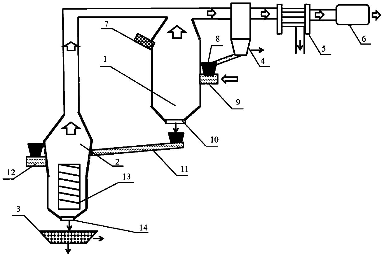
[0126] The structure diagram of the cascade waste heat recovery device using solid particle heat carrier pyrolysis and gasification is as follows figure 2 As shown, including gasification furnace 1, pyrolysis furnace 2, solid separator 3 and its auxiliary equipment, pyrolysis furnace 2, gasification furnace 1 is mainly composed of a furnace body, a feeding device system and a flue gas processing device system. The feeding device system is equipped with high particle feeding device 7, medium and low temperature particle feeding device 11, gasifier fuel nozzle 9, pyrolysis furnace fuel nozzle 12, gasifier particle outlet 10, pyrolysis furnace particle outlet 14; flue gas The treatment system is provided with a cyclo...

Embodiment 2

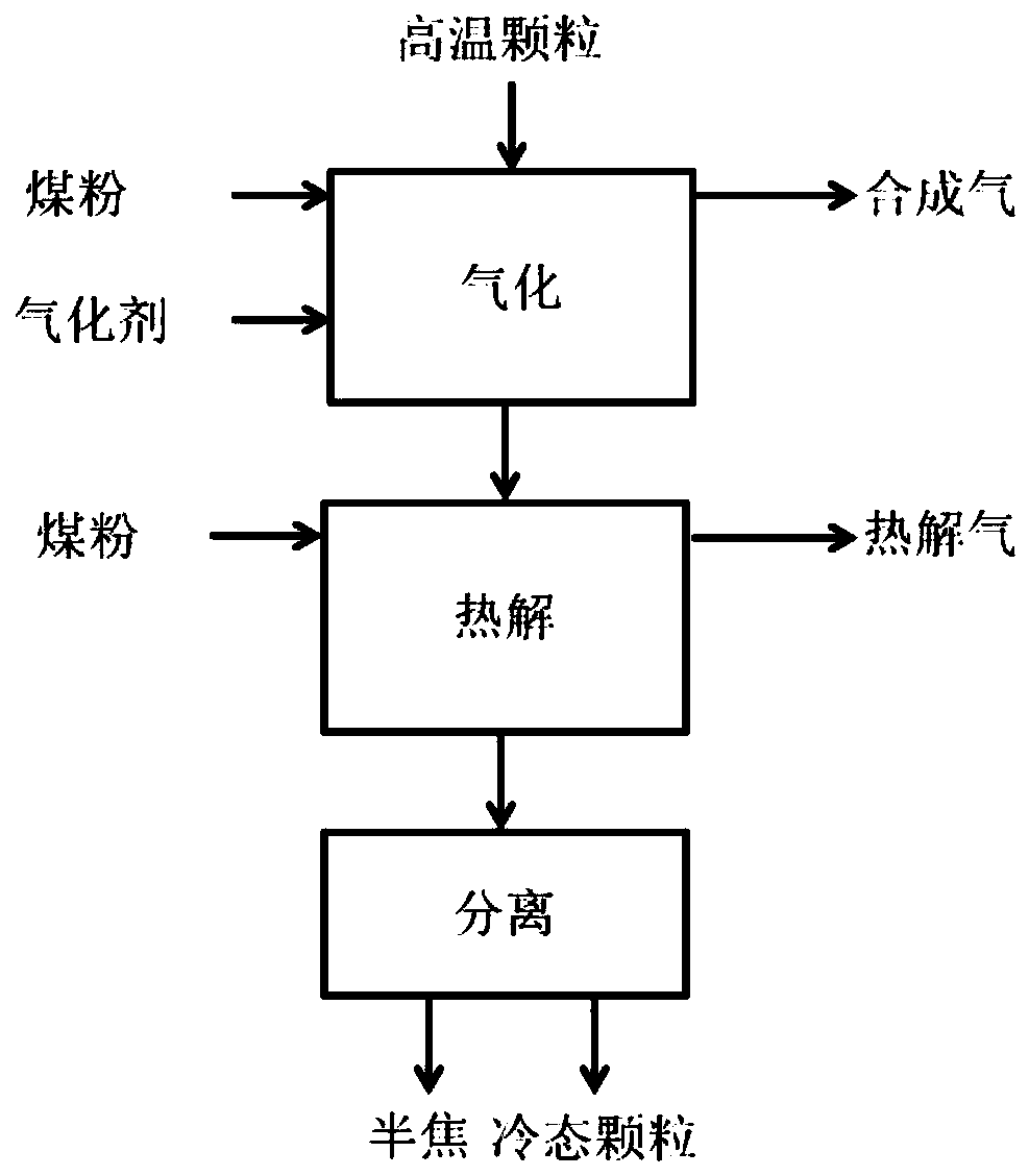
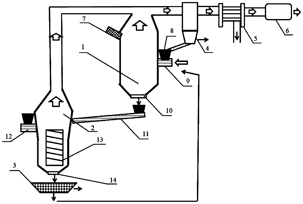
[0141] The structure diagram of the cascade waste heat recovery device using solid particle heat carrier pyrolysis and gasification is as follows Figure 4 As shown, the method for cascaded waste heat recovery using the above device, the process flow chart is as follows image 3 Shown.

[0142] Compared with Example 1, the difference lies in:

[0143] (1) In terms of process method, the fuel in the gasification furnace 1 in Example 2 is semi-coke produced in the pyrolysis furnace 2. In terms of device structure, the outlet material of the solid separator 3 enters the gasification furnace fuel nozzle 9 through a lifting device.

[0144] (2) The products in the gasifier 1 in Example 2 are combustible gas and porous coke, and the specific surface area of ​​the porous coke is 1100m 2 / g above. The combustible gas passes through the cyclone separator, gas-liquid separator and purifier to remove volatiles and condensable tar to obtain clean gas. The yield of clean gas is 30%, and the calor...

Embodiment 3

[0151] Same as Example 1, the difference lies in:

[0152] (1) The high-temperature particles in Example 3 are steel slag, the temperature of the steel slag is 1200°C, and the main components are shown in Table 6.

[0153] Table 6 Chemical composition of steel slag particles%

[0154]

[0155] (2) In Example 3, the clean gas production rate is 33%, and the clean gas heating value is about 6000kJ / m 3 ;

[0156] (4) In Example 3, the gasification agent is a certain furnace flue gas, and the composition and content are CO 2 30.8%, N 2 60.1%, O 2 0.6%, CO 3.2%, H 2 O 5%, SO 2 0.26%, other 0.04%.

[0157] (5) In Example 3, CO in the flue gas in the gasifier 1 2 The molar ratio of element C to coal powder is CO 2 / C 1:1. The ratio of the mass of high-temperature particles to the mass of pulverized coal C element is 1:0.05, and the temperature of the particles after a cooling is 800℃.

[0158] In the pyrolysis furnace, the ratio of the particle mass to the C element mass in the pulverized c...


PUM

PropertyMeasurementUnit
Particle sizeaaaaaaaaaa
Specific surface areaaaaaaaaaaa

Abstract

The invention discloses a cascade waste heat recovery device and method utilizing pyrolysis gasification of a solid particle heat carrier. The device comprises a gasification furnace, a pyrolysis furnace, a solid separator and a flue gas treatment system, the gasification furnace, the pyrolysis furnace and the solid separator are sequentially connected, and flue outlets of the gasification furnaceand the pyrolysis furnace are converged and connected with the flue gas treatment system. The method comprises the following steps: feeding high-temperature particles into the gasification furnace, feeding a carbon-containing solid waste material A into the gasification furnace under the carrying of a gasifying agent, carrying out gasification reaction to generate a combustible gas and primary cooled particles, feeding the cooled particles and a carbon-containing solid waste material B into the pyrolysis furnace for pyrolysis reaction to generate pyrolysis gas and solid semi-coke, and screening to allow the yield of the solid semi-coke to be 20-23% and the content of fixed carbon to be 77-79.1% to obtain coal gas as a gasifier fuel. According to the method, the solid particle waste heat recovery efficiency is improved to 80-84%, the efficiency is improved to 70-77%, meanwhile, combustible clean coal gas with the calorific value of 5000-7000 kJ/m3 can be obtained, and the CO2 emissionis reduced.

Description

Technical field: [0001] The invention belongs to the technical field of waste heat recovery and energy saving technology, and specifically relates to a stepped waste heat recovery device and method that utilizes solid particle heat carrier pyrolysis and gasification. Background technique: [0002] The production process of metallurgy, building materials, chemical industry and other industries has a large number of high-temperature solid bulk materials and solid particles, such as sintered ore, pellets and direct reduced iron. In addition, metallurgical slag (such as blast furnace slag, steel slag, copper slag, nickel slag, etc.) is a by-product discharged from the metal smelting process, and its discharge temperature is high (> 1200℃), contains a lot of sensible heat. At present, the traditional treatment method for metallurgical slag is water quenching method, which consumes a lot of water resources, and the environmental pollution caused by slag flushing water is also relati...

Claims


Application Information

Patent Timeline
IPC IPC(8): C10J3/58C10J3/84
CPCC10J3/58C10J3/84C10J2300/0969Y02P20/10Y02P20/129
Inventor 左宗良张敬奎罗思义于庆波周恩泽郭建翔
Owner QINGDAO TECHNOLOGICAL UNIVERSITY
Why Eureka
Try Eureka