Micro-fluidic chip and whole blood separation method based on micro-fluidic chip

A microfluidic chip and bifurcation technology, applied in the field of microfluidics, can solve the problems of high viscosity, difficult to separate and miniaturize the device, and achieve the effect of huge application potential.

Inactive Publication Date: 2020-03-27
SHENZHEN INST OF ADVANCED TECH
View PDF3 Cites 4 Cited by
  • Summary
  • Abstract
  • Description
  • Claims
  • Application Information

AI Technical Summary

Problems solved by technology

[0005] Due to the high viscosity of the blood itself, the plasma will further increase after separation, so the current whole blood separation based on the above two metho...

Method used


Image

  • Micro-fluidic chip and whole blood separation method based on micro-fluidic chip
  • Micro-fluidic chip and whole blood separation method based on micro-fluidic chip
  • Micro-fluidic chip and whole blood separation method based on micro-fluidic chip

Examples


Embodiment 1

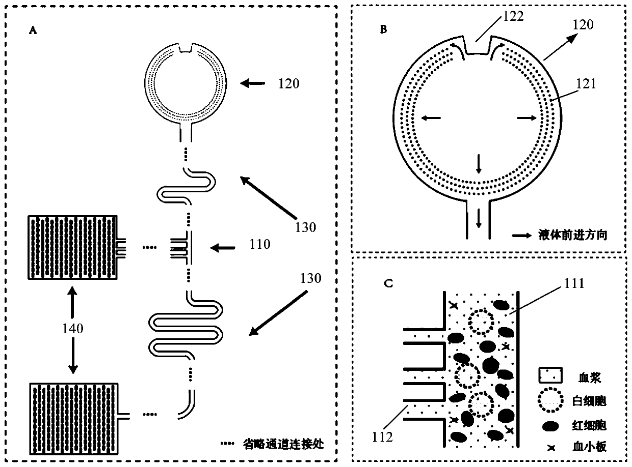
[0032] see figure 1 , is a schematic structural diagram of a microfluidic chip provided in Embodiment 1 of the present invention, including: at least one bifurcated branch unit 110, any one of the bifurcated branch units 110 includes a main channel 111 and is extended from the main channel 111 When the whole blood flows through the bifurcated branch channel 112, the blood cells are subjected to asymmetric shear force on both sides, and will choose the main channel 111 with high flow rate and small flow resistance. The channel continues to move forward, and part of the blood plasma enters the bifurcated branch channel 112 .

[0033] The specific structure of each component and the way of connecting with each other will be described in detail below.

[0034] see figure 1 Middle C and figure 2 A schematic structural view and a partially enlarged view of any one of the bifurcated branch units 110 provided in this embodiment.

[0035] In this embodiment, the bifurcated branch ...

Embodiment 2

[0054] In this embodiment, the microfluidic chip provided by the present invention can be a material that can be manufactured by micro-nano processing methods, such as silicon-based materials such as single crystal silicon, silicon oxide, and silicon nitride, or glass materials such as quartz. Or it can be polymer materials such as polydimethylsiloxane (Polydimethylsiloxane, PDMS), polymethyl methacrylate (Polymethyl methacrylate, PMMA). For different materials and different sizes of channels in the chip, the preparation methods include but are not limited to laser etching, 3D printing, photolithography, plasma etching and other micro-nano processing methods.

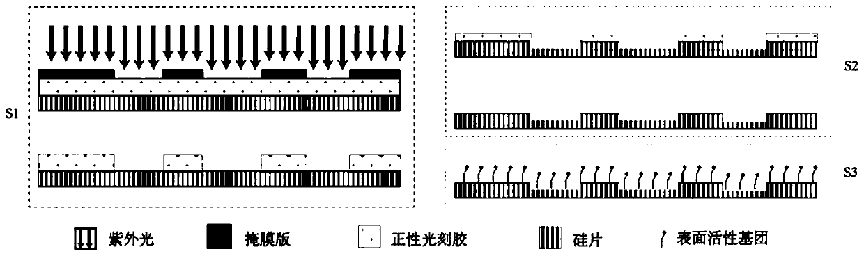
[0055] see image 3 , is a process schematic diagram of the microfluidic chip provided by the embodiment of the present invention, and the specific steps are as follows:

[0056] S1: Hang coat a layer of photoresist on the substrate, use the corresponding microchannel mask plate to form a microchannel etching window by...

Embodiment 3

[0067] see Figure 4 , the present invention also provides a whole blood separation method based on the microfluidic chip, comprising the following steps:

[0068] Step S110: adding a blood sample into the sample inlet unit 120 of the microfluidic chip;

[0069] It can be understood that the blood samples used for the whole blood separation realized by the microfluidic chip can be untreated blood, anticoagulated blood, diluted blood, etc.

[0070] Step S120: under the action of the flow resistance adjustment unit 130 provided at the front end and the rear end of the bifurcated branch channel 112, respectively perform flow resistance adjustment on the front end and the rear end of the bifurcated branch channel 112;

[0071] Step S130: when the blood flows through the bifurcated branch channel 112, due to the asymmetrical shear force on both sides, the blood cells will be oriented to enter the main channel 111, and the plasma will enter the bifurcated branch channel 112;

[00...


PUM

PropertyMeasurementUnit
Widthaaaaaaaaaa
Widthaaaaaaaaaa
Diameteraaaaaaaaaa

Abstract

The invention provides a micro-fluidic chip. When total blood flow passes through a bifurcated branch channel port, blood cells are subjected to asymmetric shearing force on two sides, the blood cellsselect a main channel with the large flow speed and the small flow resistance to continue to advance, and part of blood plasma can enter a bifurcated branch channel. According to the micro-fluidic chip, the micro-fluidic chip constructed through a bifurcated multi-branch structure can achieve whole blood separation without exogenous power. When the micro-fluidic chip performs flow resistance adjustment through a flow resistance adjusting unit 130 located in the bifurcated branch channel, the collection efficiency of the blood plasma is adjusted. According to the micro-fluidic chip, capillarydriving force is provided through a capillary pump unit 140 located at a tail end, the functions of quantifying and collecting plasma/serum are achieved, and finally on-chip self-driven whole blood separation is achieved. The micro-fluidic chip provided by the invention shows huge application potential in the field of integrated and micro-miniaturized bedside instant detection.

Description

technical field [0001] The invention relates to the technical field of microfluidic technology, in particular to a microfluidic chip and a whole blood separation method based on the microfluidic chip. Background technique [0002] As the most popular sample in clinical diagnosis, blood contains a large proportion of disease markers in the human body. It is suitable for various tests such as immunodiagnosis, clinical biochemistry, and molecular diagnosis. It is currently the most commonly used sample object. Most of the tests for blood need to remove blood cells from the blood for plasma or serum extraction in the sample pretreatment stage, or need to enrich the cells in the blood for related next-step tests. Different from the traditional whole blood separation methods such as centrifugation, filtration and salting out, in the emerging fields of in vitro diagnostics such as microfluidic technology and lab-on-a-chip, corresponding new miniaturized and highly integrated whole ...

Claims


Application Information

Patent Timeline
IPC IPC(8): B01L3/00
CPCB01L3/502753
Inventor 陈思卉陈希杨慧张翊
Owner SHENZHEN INST OF ADVANCED TECH
Why Eureka
Try Eureka