Packaged large-area perovskite solar cell

A solar cell and perovskite technology, applied in the field of solar cells, can solve the problems of unsuitability for single-chip module power generation, large series resistance, insufficient module voltage, etc. Effect

Pending Publication Date: 2020-06-09
SHANGHAI INST OF CERAMIC CHEM & TECH CHINESE ACAD OF SCI +2
View PDF2 Cites 3 Cited by
  • Summary
  • Abstract
  • Description
  • Claims
  • Application Information

AI Technical Summary

Problems solved by technology

Although the above method provides a perovskite solar cell module composed of single-cell perovskite solar cells connected in series or in parallel, the series structure inside the series module will lead to a large series resistance, and the parallel structure will lead to insufficient module voltage. Multiple dispersed modules are required to be connected in series and parallel to form an overall assembly, which is not suitable for monolithic module power generation

Method used


Image

  • Packaged large-area perovskite solar cell
  • Packaged large-area perovskite solar cell
  • Packaged large-area perovskite solar cell

Examples


Embodiment 1

[0079] made as Figure 5 The battery with 19 small units in series and 2 large units in parallel, the specific steps are as follows.

[0080] (1) Use a laser to make holes on the transparent conductive substrate, and etch away the conductive FTO layer to ensure infinite resistance between units.

[0081] (2) Use acetone, alkaline detergent, deionized water, and acetone to ultrasonically clean the FTO glass for ten minutes, and finally blow dry.

[0082] (3) Preparation of TiO on FTO glass substrate 2 Dense layer, the solvent is terpineol, which includes the following components: 1.5ml tetraisopropyl titanate, 3.5g ethyl cellulose, 80ml terpineol, coated on a clean FTO substrate, in a muffle furnace at 510 ℃ sintering for 30min.

[0083] (4) On the dense layer, screen-print titanium dioxide paste as the electron transport layer, with a solid content of 10%, solvent terpineol, and sinter in a muffle furnace at 510 ° C for 30 min.

[0084] (5) On the electron transport layer,...

Embodiment 2

[0098] The preparation and packaging process of the battery is the same as that of Example 1, and will not be repeated here.

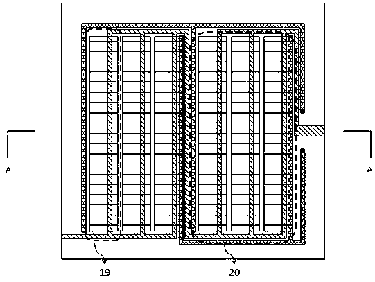
[0099] Specific preparation such as Figure 6 A structure in which 4 small units are connected in series and 11 large units are connected in parallel can be formed, for example, as follows:

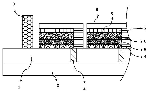
[0100] The short side of the small unit is close to the etching line, and the part of the small unit (hole blocking layer, electron transport layer, insulating layer and hole transport layer) except the counter electrode (positive electrode) covers the etching line side (upper side) On the conductive layer (negative electrode) on the transparent conductive substrate, the counter electrode vertically spans the etched line to the other side (lower side), covering the conductive grid line (negative electrode) on the lower side of the etched line. The positive and negative poles in the unit are separated by an insulating layer. The anode of the unit above the etchin...

Embodiment 3

[0102] The preparation and packaging process of the battery is the same as that of Example 1, and will not be repeated here.

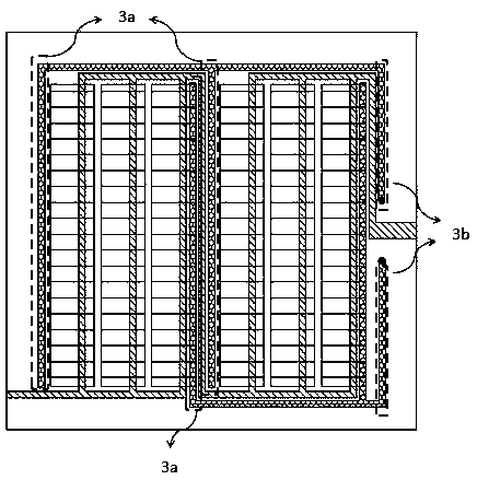
[0103] Specific preparation such as Figure 4 A structure in which 3 small units are connected in parallel and 2 large units are connected in series can be formed, for example, as follows:

[0104] The middle longitudinal etching line divides the conductive layer on the transparent conductive substrate into two large units, left and right. In the large unit on the left, the conductive grid lines are distributed in the small unit gap, collecting electrons (negative pole) on the conductive layer to the upper left hole to form the negative pole of the module; the short side of the lower side of the three small units is close to the etching line, and the small unit The part (hole blocking layer, electron transport layer, insulating layer, and hole transport layer) other than the counter electrode (positive electrode) covers the conductive layer (negative ...


PUM

PropertyMeasurementUnit
widthaaaaaaaaaa
thicknessaaaaaaaaaa

Abstract

The invention relates to a packaged large-area perovskite solar cell, which comprises a transparent substrate, a conductive layer formed on the transparent substrate, non-conductive etching lines formed on the conductive layer, conductive grid lines arranged on the conductive layer through printing and a perovskite solar cell module arranged on the conductive layer, wherein the cell module comprises two or more large units, and each large unit comprises two or more small units; the large units are connected in parallel and the small units are connected in series through the etching lines and the conductive grid lines, or the large units are connected in series and the small units are connected in parallel. The plurality of large units on the same transparent substrate are connected in parallel so as to reduce the series resistance of the cell and improve the working current, and the large units are further connected in series by a plurality of small units, so that and the voltage of the cell is improved; or the plurality of large units are connected in series so as to improve the voltage of the cell, and the large units are further connected in parallel by the plurality of small units, so that the series resistance of the cell is reduced, and the working current is increased.

Description

technical field [0001] The invention relates to the field of solar cells, in particular to a packaged large-area perovskite solar cell. Background technique [0002] In the past 10 years, perovskite solar cells have developed rapidly due to their outstanding advantages. Specifically, perovskite solar cells are simple to manufacture, low in cost, and flexible and transparent cells can be prepared. At the same time, it also has a relatively suitable band gap width, and the color of the battery can be controlled by changing its band gap to prepare a colored battery. Furthermore, the charge diffusion length is up to micron level, and the charge lifetime is long. In addition, its unique defect characteristics enable perovskite crystal materials to exhibit both n-type semiconductor properties and p-type semiconductor properties, so its applications are more diverse. Therefore, perovskite solar cells and related materials have become a research direction in the field of photovolt...

Claims


Application Information

Patent Timeline
Patent Type & Authority Applications(China)
IPC IPC(8): H01L51/42H01L51/44
CPCH10K30/151H10K30/80H10K30/81H10K30/00H10K30/88Y02E10/549
Inventor 杨松旺陈宗琦寿春晖陈薪羽沈曲洪凌郑渭建关键褚晓虹林王坚邓芙蓉
Owner SHANGHAI INST OF CERAMIC CHEM & TECH CHINESE ACAD OF SCI
Why Eureka
Try Eureka