CO2 electroreduction reaction control method based on electrode solution system
A control method, CO2 technology, applied in the direction of electrode shape/type, electrode, electrolysis process, etc., can solve the problem of gradual change of product selectivity
- Summary
- Abstract
- Description
- Claims
- Application Information
AI Technical Summary
Problems solved by technology
Method used
Image
Examples
Embodiment 1
[0029] Example 1: CO 2 RR reaction system and reaction control method
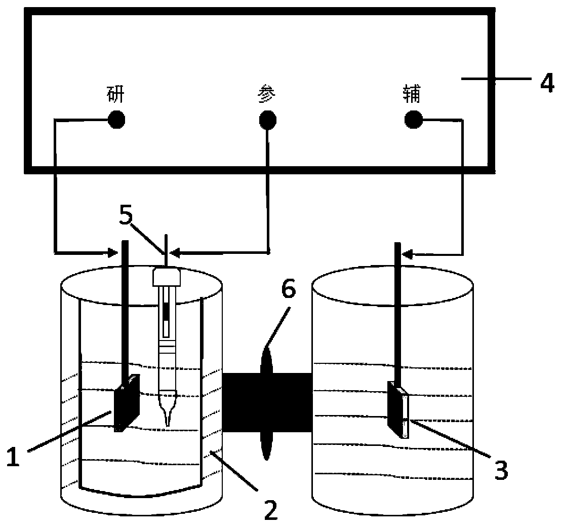
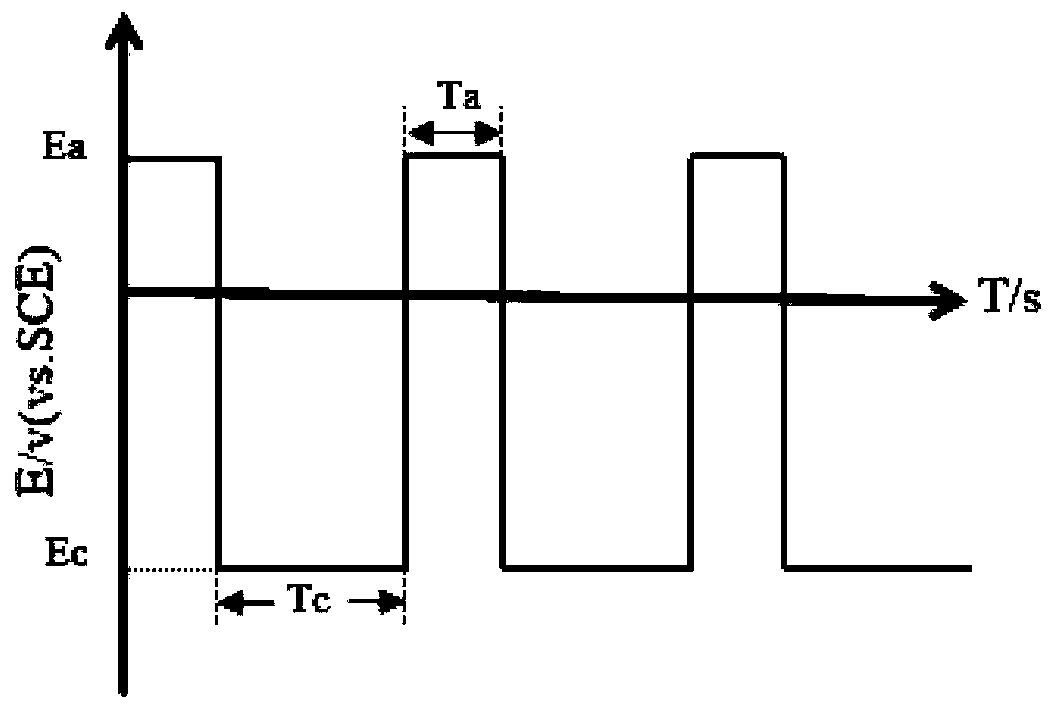
[0030] CO 2 RR can be carried out in an H-type temperature-controllable electrolytic cell, and its structure is composed of an anode chamber, a cathode chamber and an electrolyte membrane, such as figure 1 shown. The catholyte, working electrode (Cu-based electrocatalytic material) and reference electrode (saturated calomel electrode, SCE) are built in the cathode chamber; the electrolyte membrane can be a proton exchange membrane (such as: Membrane); the anode compartment is placed with an auxiliary electrode (or counter electrode) and an anolyte composed of an inert oxygen-evolving material. figure 2 The schematic diagrams of the operating methods of periodic potential and current step are given respectively. Among them, T a with T c The sum is a redox cycle.
Embodiment 2
[0031] Example 2: The surface morphology of the electrode solution interface constructed of Cu foil and different electrolyte solutions under the environment of periodic potential steps.
[0032] Cu foil and PBS solution, 0.5mol L -1 KHCO 3 solution and CO 2 Saturated 0.5mol·L -1 KHCO 3 The interface system formed by the solution, at 10℃, under the periodic potential step (E a =0.5V, T a =5s,E c =-2.2V, T c =70s) surface morphology after 30 minutes, the results are as follows image 3 shown.
[0033] It can be seen that in the PBS solution, irregular nano-copper particles are sparsely distributed on the surface of the copper foil, and the particle size is 30±10nm~80±10nm; 3 In the aqueous solution, the surface of the copper is distributed with more nano-copper with a shape similar to a pyramid, and its particle size ranges from 90±10nm to 240±10nm; in CO 2 saturated KHCO 3 In the aqueous solution, nano-copper in the shape of a quadrangular pyramid is densely distrib...
Embodiment 3
[0034] Example 3: Cu foil with CO 2 Saturated 0.5mol·L -1 KHCO 3 The surface morphology of the electrode-solution interface system formed by the solution under different periodic potential step operating environments.
[0035] Figure 4 Cu foil and CO are given respectively 2 Saturated 0.5mol·L -1 KHCO 3 The surface morphology of the electrode-solution interface system formed by the solution after 30 minutes of periodic potential step operation mode. The pretreatment process of Cu foil is: in phosphoric acid with a volume concentration of 85% at a current density of 50mA cm -2 Perform electropolishing treatment and rinse with deionized water; take it out and place it in absolute ethanol for ultrasonic treatment and rinse with deionized water.
[0036] Figure 4 (a) shows the CO 2 RR control mode is 10℃, periodic potential step (E a =1.0V, T a =5s,E c =-2.2V, T c =30s) Cu foil surface after 30 minutes. It can be seen that cubic copper particles with a particle siz...
PUM
 Abstract
Description
Claims
Application Information
 - R&D
- Intellectual Property
- Life Sciences
- Materials
- Tech Scout
- Unparalleled Data Quality
- Higher Quality Content
- 60% Fewer Hallucinations
Browse by: Latest US Patents, China's latest patents, Technical Efficacy Thesaurus, Application Domain, Technology Topic, Popular Technical Reports.
© 2025 PatSnap. All rights reserved.Legal|Privacy policy|Modern Slavery Act Transparency Statement|Sitemap|About US| Contact US: help@patsnap.com


