A co-based electrode solution system 2 Electroreduction reaction control method

A control method and technology of electrolyte solution, applied in the direction of electrode shape/type, electrode, electrolysis components, etc., can solve the problem of gradual change of product selectivity, and achieve the effect of controllable conversion

Active Publication Date: 2021-11-05
DALIAN UNIV OF TECH
View PDF11 Cites 0 Cited by
  • Summary
  • Abstract
  • Description
  • Claims
  • Application Information

AI Technical Summary

Problems solved by technology

However, the current preparation of Cu-based catalysts mostly adopts ex-situ physical, chemical, and electrochemical methods. 2 During the RR operation, it is impossible to regenerate the catalytic material or adjust the structure in situ for the gradual change of product selectivity

Method used


Image

  • A co-based electrode solution system  <sub>2</sub> Electroreduction reaction control method
  • A co-based electrode solution system  <sub>2</sub> Electroreduction reaction control method
  • A co-based electrode solution system  <sub>2</sub> Electroreduction reaction control method

Examples


Embodiment 1

[0029] Example 1: CO 2 RR reaction system and reaction control method

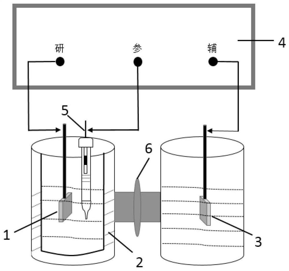
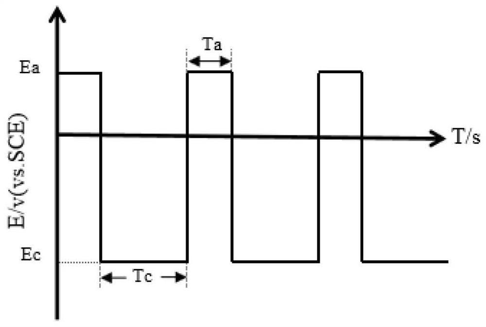
[0030] CO 2 RR can be carried out in an H-type temperature-controllable electrolytic cell, and its structure is composed of an anode chamber, a cathode chamber and an electrolyte membrane, such as figure 1 shown. The catholyte, working electrode (Cu-based electrocatalytic material) and reference electrode (saturated calomel electrode, SCE) are built in the cathode chamber; the electrolyte membrane can be a proton exchange membrane (such as: Membrane); the anode compartment is placed with an auxiliary electrode (or counter electrode) and an anolyte composed of an inert oxygen-evolving material. figure 2 The schematic diagrams of the operating methods of periodic potential and current step are given respectively. Among them, T a with T c The sum is a redox cycle.

Embodiment 2

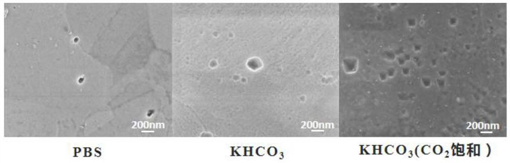
[0031] Example 2: The surface morphology of the electrode solution interface constructed of Cu foil and different electrolyte solutions under the environment of periodic potential steps.

[0032] Cu foil and PBS solution, 0.5mol L -1 KHCO 3 solution and CO 2 Saturated 0.5mol·L -1 KHCO 3 The interface system formed by the solution, at 10℃, under the periodic potential step (E a =0.5V, T a =5s,E c =-2.2V, T c =70s) surface morphology after 30 minutes, the results are as follows image 3 shown.

[0033] It can be seen that in the PBS solution, irregular nano-copper particles are sparsely distributed on the surface of the copper foil, and the particle size is 30±10nm~80±10nm; 3 In the aqueous solution, the surface of the copper is distributed with more nano-copper with a shape similar to a pyramid, and its particle size ranges from 90±10nm to 240±10nm; in CO 2 saturated KHCO 3 In the aqueous solution, nano-copper in the shape of a quadrangular pyramid is densely distri...

Embodiment 3

[0034] Example 3: Cu foil with CO 2 Saturated 0.5mol·L -1 KHCO 3 The surface morphology of the electrode-solution interface system formed by the solution under different periodic potential step operating environments.

[0035] Figure 4 Cu foil and CO are given respectively 2 Saturated 0.5mol·L -1 KHCO 3 The surface morphology of the electrode-solution interface system formed by the solution after 30 minutes of periodic potential step operation mode. The pretreatment process of Cu foil is: in phosphoric acid with a volume concentration of 85% at a current density of 50mA cm -2 Perform electropolishing treatment and rinse with deionized water; take it out and place it in absolute ethanol for ultrasonic treatment and rinse with deionized water.

[0036] Figure 4 (a) shows the CO 2 RR control mode is 10℃, periodic potential step (E a =1.0V, T a =5s,E c =-2.2V, T c =30s) Cu foil surface after 30 minutes. It can be seen that cubic copper particles with a particle siz...


PUM

PropertyMeasurementUnit
particle diameteraaaaaaaaaa

Abstract

The invention relates to a CO2 electroreduction reaction control method based on an electrode solution system, which can realize the production of CH 4 selective modulation. Wherein, the electrode solution system is an interface system in which copper-based electrocatalytic materials (including: copper foil, copper mesh, nano-copper and carbon-supported nano-copper particles) are in contact with an electrolyte solution. In the temperature range of 0-60 °C, the interface system can control the periodic step change of the potential, which can realize the selective preparation of the catalyst crystal plane and the controllable preparation of the grain size, and then realize the CO 2 Modulation of electroreduction product selectivity. Wherein, the modulation range of the faradaic efficiency of methane is 5.5%-79%. CO involved in the present invention 2 The control method of the electroreduction reaction can not only tune the product CH 4 selectivity, but also to increase the CO 2 Stability of the electroreduction reaction for CO 2 Large-scale application of electroreduction technology.

Description

technical field [0001] The present invention relates to CO in nature 2 resource conversion, specifically a CO based electrode solution system with controllable hydrocarbon product selectivity 2 Electroreduction reaction (CO 2 RR) control method. Background technique [0002] CO 2 Electroreduction reaction (CO 2 RR) can convert CO under normal pressure and near normal temperature 2 Direct conversion into fuels and useful chemicals is a key technology to realize the "carbon cycle" in nature and alleviate many environmental problems. This technology has received the most attention in recent years due to its advantages such as simple system structure, environmental friendliness, and mild reaction conditions. Under the action of an electric field, CO 2 Can be reduced to CO, CH 4 、C 2 h 4 Gas phase products such as formic acid, ethanol and other liquid phase products. Among them, gaseous hydrocarbon products have higher combustion heat and economic added value. [0003...

Claims


Application Information

Patent Timeline
Patent Type & Authority Patents(China)
IPC IPC(8): C25B3/03C25B3/26C25B11/075C25B11/02C25B11/03C25B3/25
CPCC25B11/04C25B3/25C25B11/031
Inventor 毛庆赵健李冰玉刘松徐可一曹自强郭唱黄延强
Owner DALIAN UNIV OF TECH
Why Eureka
Try Eureka