Light absorption material glass for optical fiber image transmission element and preparation method thereof

A fiber optic image transmission and light absorption technology, which is applied in glass manufacturing equipment, optical components, glass molding, etc., can solve problems such as poor light absorption performance, poor imaging contrast, and low efficiency of stray light absorption

Active Publication Date: 2020-07-14
CHINA BUILDING MATERIALS ACAD
View PDF4 Cites 2 Cited by
  • Summary
  • Abstract
  • Description
  • Claims
  • Application Information

AI Technical Summary

Problems solved by technology

[0005] Ordinary light-absorbing glass still has a high transmittance in the visible light range at a thickness of 0.5mm. As the thickness decreases, the transmittance will gradually increase. The problems of low absorption efficiency of stray light and poor imaging contrast are due to the fact that most of these light-absorbing glass materials are made of Fe 2 o 3 As a light-absorbing colorant, although Fe 3+ Ions have good light-absorbing performance, but their light-absorbing range is mainly concentrated in the infrared region, and their light-absorbing performance is poor in the visible light region. However, the fluorescent screen of the optical fiber image transmission component used in the low-light night vision device uses P20 phosphor powder , its luminescent wavelength is in the range of 510-560nm, mainly green light wavelength; and the use of Fe 3+ When ions are used as light absorbers, due to Fe 3+ Ions are variable valence element ions, and the valence state of ions is prone to change at high temperatures, and it is difficult to maintain an oxidized state in glass, especially for optical fiber filaments with a fiber diameter of less than 6 μm, ferric oxide Fe 2 o 3 The coloring of the coloring will become unstable or even fade during the high-temperature drawing process, and a reducing atmosphere is required to obtain a good light absorption effect. What is more serious is that the coloring ions will diffuse into the cortex glass of the optical fiber, so that the optical fiber is completely The reflection mechanism weakens or disappears, which directly affects the light absorption effect, especially the light-absorbing material glass used in optical fiber imaging components, and even "poisons" the photocathode material, which has a serious impact on improving the image quality of optical fiber imaging components , unable to meet the application requirements of improving the definition and contrast of optical fiber image transmission components

Method used


Image

  • Light absorption material glass for optical fiber image transmission element and preparation method thereof
  • Light absorption material glass for optical fiber image transmission element and preparation method thereof
  • Light absorption material glass for optical fiber image transmission element and preparation method thereof

Examples


Embodiment 1

[0059] First, select the raw materials according to the glass composition of Example 1 in Table 1 and mix them evenly to obtain the raw material mixture. The raw material requirements:

[0060] Quartz sand or crystal powder (high purity, less than 1% of 150μm sieve, 30% of 45μm sieve, Fe 2 o 3 Content less than 1ppm), alumina powder (analytical pure, average particle size 50μm), boric acid or boric anhydride (400μm sieve is less than 10%, 63μm sieve is less than 10%), lithium carbonate (analytical pure, purity ≥ 99.0%), Sodium Carbonate (Industrial Soda Ash), Potassium Carbonate or Potassium Nitrate (Analytical Pure, Purity≥99.0%), Basic Magnesium Carbonate (Chemical Pure, Average Particle Size 50μm), Calcium Carbonate (Analytical Pure, Average Particle Size 250μm ), Manganese Dioxide (Analytical Pure), Vanadium Oxide (Analytical Pure), Neodymium Oxide (Analytical Pure), Cobalt Oxide (Analytical Pure), Nickel Oxide (Analytical Pure).

[0061] And the oxides of variable valen...

Embodiment 2

[0065] The glass composition refers to Example 2 in Table 1. Using the same raw materials and raw material requirements as in Example 1, weigh part of the raw material mixture and put it into a quartz crucible, and melt it at a temperature of 1400 ° C for 10 hours. During the glass melting process, the glass is Stir 2 to 3 times to make the glass melt evenly. After the glass is melted, the glass melt is quenched. After quenching, the clinker glass is dried and pulverized to obtain clinker glass powder. The raw material mixture of Example 2 is mixed evenly with a mass ratio of 1:3, put into a quartz crucible; melted at 1460°C for 5 hours, and 2-3 times during the glass melting process Stir, after the glass is melted, clarify at 1450°C for 3 hours, cast the molten glass into specified specifications, vibrate evenly, and then anneal to obtain the light-absorbing material glass of the present invention.

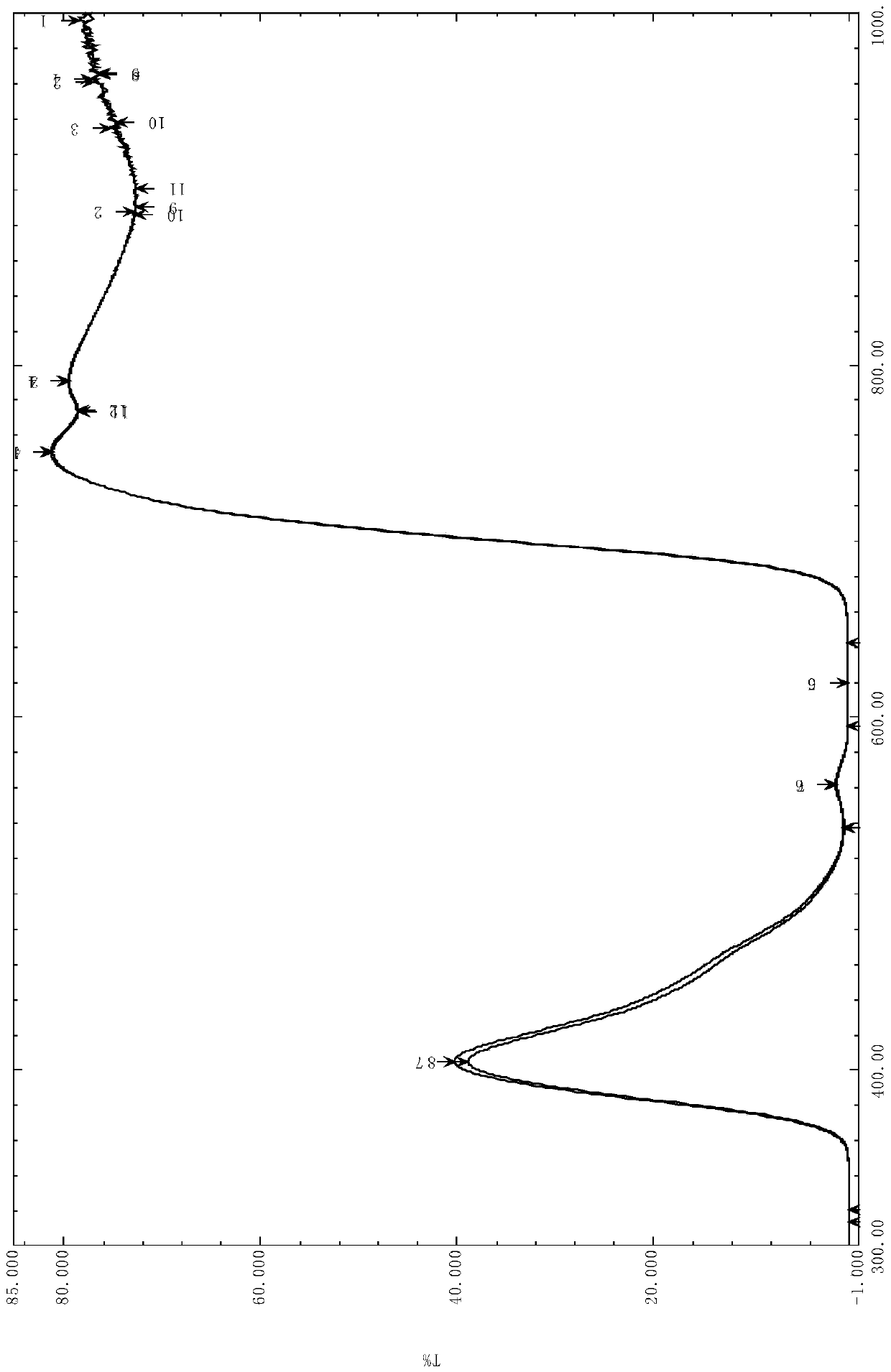
[0066] The basic properties of the sample are shown in Table 1. The visible ...

Embodiment 3

[0068] The actual composition of the glass refers to Example 3 in Table 1. Using the same raw materials and raw material requirements as in Example 1, weigh part of the raw material mixture and put it into a quartz crucible, and melt it at 1600 ° C for 6 hours. During the glass melting process, the glass Stir 2 to 3 times to make the glass melt evenly. After the glass is melted, quench the glass melt. After quenching, dry and pulverize the clinker glass to obtain clinker glass powder. Then mix the clinker glass powder with the 1 The raw material composition of Example 3 is mixed and the raw material mixture is mixed evenly with a mass ratio of 1:2.5, and put into a quartz crucible; melted at 1500 ° C for 3 hours, and 2-3 After the glass is melted, it is clarified at a temperature of 1460°C for 2 hours, and the molten glass is cast into a specified specification, and then annealed to obtain the light-absorbing material glass of the present invention.

[0069] The basic properties...


PUM

PropertyMeasurementUnit
Crystallization temperatureaaaaaaaaaa
Thermal expansion coefficientaaaaaaaaaa
Crystallization temperatureaaaaaaaaaa

Abstract

The invention discloses light absorption material glass for an optical fiber image transmission element and a preparation method of the light absorption material glass. The light absorption material glass is composed of the following components in percentage by mole: SiO2 70-79%, Al2O3 0.1-5.0%, B2O3 0.1-6.0%, Li2O 0.1-1.0%, Na2O 5.0-8.0%, K2O 5.0-8.0%, MgO 0.1-1.0%, CaO 0.1-5.0%, MnO2 1.0-5.0%, V2O5 0.1-5.0%, Nd2O3 0.1-1.0%, CoO 0-1.0%, NiO 0-1.0%. The light absorption material glass provided by the invention is applied to the optical fiber image transmission element, the imaging contrast ratio and definition of the optical fiber image transmission element can be improved, and the fused light absorption material glass has the advantages of no stone or bubble hole in the glass, no crystallization after heat preservation for 6 hours at 850 DEG C, good crystallization resistance, excellent chemical stability and the like.

Description

technical field [0001] The invention relates to the field of glass materials, in particular to a light-absorbing material glass used for optical fiber image transmission components and a preparation method thereof. Background technique [0002] Fiber optic image transmission components include fiber optic panels, fiber optic image inverters, fiber optic cones, fiber optic image transmission bundles, etc., which are photoelectric imaging components with excellent performance. Clear and real, with zero thickness optically, simple structure, small size, light weight, good air tightness, small distortion, less spots, small inter-stage coupling loss, high coupling efficiency and improved edge image quality, etc. The most typical application of optical fiber image transmission components is as the optical input and output windows of low-light image intensifiers, which play an important role in improving the quality of imaging devices, and are widely used in various fields such as ...

Claims


Application Information

Patent Timeline
IPC IPC(8): C03C4/08C03C3/091C03B19/02G02B1/00
CPCC03C4/08C03C3/091C03B19/02G02B1/00
Inventor 贾金升张磊张弦汤晓峰石钰许慧超于浩洋张敬樊志恒宋普光王爱新洪常华赵越
Owner CHINA BUILDING MATERIALS ACAD
Why Eureka
Try Eureka