A kind of anti-CMAS double-layer structure protective coating, thermal barrier coating multilayer structure and preparation method thereof

A double-layer structure and protective coating technology, applied in the direction of coating, metal material coating process, superimposed layer plating, etc., can solve the problem of single material and single structure not meeting comprehensive performance requirements, failure, low thermal expansion coefficient, etc. problem, achieve the effect of reducing interface mismatch, not easy to change or fail, and strong chemical stability

Active Publication Date: 2021-02-19
BEIHANG UNIV
View PDF1 Cites 1 Cited by
  • Summary
  • Abstract
  • Description
  • Claims
  • Application Information

AI Technical Summary

Problems solved by technology

In the above technical scheme, yttria-stabilized zirconia (YSZ) and alumina are used as micro-nano structure layer materials, but YSZ itself is prone to chemical reactions with CMAS to cause phase change instability and failure of the coating, while oxidized Aluminum has problems such as low thermal expansion coefficient and high brittleness. Although the micro-nano structure can significantly reduce the possibility of molten CMAS penetrating into the coating, there is still the possibility of tiny molten CMAS droplets penetrating into the coating.
[0008] Generally speaking, although technologies such as inert barrier layers have been initially applied to the surface of thermal barrier coatings to protect CMAS corrosion, due to the fact that thermal barrier coatings need to have high heat insulation / thermal shock resistance / anti-CMAS corrosion / anti-corrosion Molten salt corrosion / coefficient of thermal expansion matched with the base material, etc., while the single material and single structure in the prior art do not meet the above comprehensive performance requirements, so building a thermal barrier coating structure with comprehensive performance is a major issue in the field of thermal barrier coatings problem

Method used


Image

  • A kind of anti-CMAS double-layer structure protective coating, thermal barrier coating multilayer structure and preparation method thereof
  • A kind of anti-CMAS double-layer structure protective coating, thermal barrier coating multilayer structure and preparation method thereof
  • A kind of anti-CMAS double-layer structure protective coating, thermal barrier coating multilayer structure and preparation method thereof

Examples


preparation example Construction

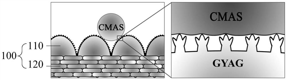
[0058] For the preparation method of the multilayer structure of the thermal barrier coating, the bonding layer 300 can be prepared by electron beam physical vapor deposition (EB-PVD), multi-arc ion plating or aluminizing after electroplating Pt; atmospheric plasma spraying (APS ), electron beam physical vapor deposition (EB-PVD) or plasma physical vapor deposition (PS-PVD) method to prepare the first ceramic layer 210; using electron beam physical vapor deposition or plasma physical vapor deposition method, on the first ceramic layer The second ceramic layer 220 is prepared on the 210; the anti-CMAS double-layer structure protective coating 100 is prepared by plasma physical vapor deposition (PS-PVD).

[0059] Further, the present application also provides a method for preparing a thermal barrier coating multilayer structure with excellent comprehensive performance with an anti-CMAS double-layer structure protective coating 100, comprising the following steps: sequentially for...

Embodiment 1

[0075] Preparation on the surface of the superalloy substrate 400: NiCoCrAlY bonding layer 300 (EB-PVD) + YSZ first ceramic layer 210 (EB-PVD) + YAG anti-CMAS double-layer protective coating (PS-PVD) thermal barrier coating Layer structure, the specific steps are as follows:

[0076] In the first step, the superalloy substrate 400 is ground and then polished, and the surface is pretreated by sandblasting to prepare for coating preparation. Said superalloy is the second generation single crystal alloy (DD6, N5) or directional superalloy DZ125.

[0077] In the second step, the NiCoCrAlY bonding layer 300 is prepared on the substrate 400 by electron beam physical vapor deposition method, and the preparation steps are as follows:

[0078] (1) Use high-purity nickel (Ni), cobalt (Co), chromium (Cr), aluminum (Al) and yttrium (Y), according to the design composition ratio, the Co content is 22wt.%, the Cr content is 20wt.%, and the Al content is 15wt.%, the Y content is 1.46wt.%, an...

Embodiment 2

[0097] On the surface of the superalloy substrate 400, prepare a composite structure thermal barrier coating of PtNiAl bonding layer 300 (electroplating Pt aluminized) + first ceramic layer 210YSZ (PS-PVD) + GYAG protective coating (PS-PVD), the specific steps are as follows :

[0098] In the first step, the superalloy substrate 400 is polished on 120#, 320#, 400#, 800#, 1000#, 1500# water sandpaper in sequence, and then polished, and the surface blasting pretreatment is done for coating preparation. Prepare. Said superalloy is single crystal alloy (DD6, N5, IC21, DD9, IC10) or directional superalloy DZ125 alloy.

[0099] In the second step, a PtNiAl bonding layer 300 is prepared on the alloy substrate 400 by means of electroplating and embedding infiltration. The preparation steps of the PtNiAl bonding layer 300 are as follows:

[0100] Configure the electroplating solution of Pt, the selected composition is: Platinum diammonium nitrite (Pt(NH 3 ) 2 (NO 2 ) 2 ) content ...


PUM

PropertyMeasurementUnit
thicknessaaaaaaaaaa
thicknessaaaaaaaaaa
thicknessaaaaaaaaaa

Abstract

The application discloses an anti-CMAS double-layer structure protective coating, comprising a micro-nano structure layer and a dense layer connected to the micro-nano structure layer, the surface of the micro-nano structure layer has a micro-nano structure, and the micro-nano structure layer The structure includes a micron-scale protrusion structure and a nano-scale protrusion structure on the micron-scale protrusion, and the coating material of the anti-CMAS double-layer structure protective coating is yttrium aluminum garnet and rare earth One or both of the modified yttrium aluminum garnets. The application also discloses a preparation method for preparing an anti-CMAS double-layer structure protective coating by using PS‑PVD technology. The application also discloses a thermal barrier coating multilayer structure with the anti-CMAS double-layer structure protective coating.

Description

technical field [0001] The invention relates to the technical field of thermal barrier coating corrosion and protection, in particular to an anti-CMAS double-layer structure protective coating, a thermal barrier coating multilayer structure and a preparation method thereof. Background technique [0002] Thermal Barrier Coatings (TBCs), together with high-temperature structural materials and high-efficiency air cooling, are the three key technologies of the turbine blades, the core hot-end components of advanced aero-engines. The application of thermal barrier coatings in aero-engines has greatly improved the engine's operating temperature and high-temperature gas corrosion resistance, greatly prolonging the service life of aero-engines, and has important military significance. As the service temperature and life of aero-engines continue to increase, one of the main chemical components is CaO-MgO-Al 2 o 3 -SiO 2 (referred to as CMAS) environmental deposits are increasingly...

Claims


Application Information

Patent Timeline
Patent Type & Authority Patents(China)
IPC IPC(8): C23C14/30C23C14/16C23C14/08C23C14/58C23C28/00C23C10/48C25D3/50
CPCC23C10/48C23C14/08C23C14/083C23C14/16C23C14/30C23C14/5806C23C28/3215C23C28/322C23C28/3455C25D3/50
Inventor 郭洪波郭奕谦何雯婷魏亮亮宫声凯徐惠彬
Owner BEIHANG UNIV
Why Eureka
Try Eureka