Oxygen reduction electrocatalyst material and preparation method thereof

An electrocatalyst and catalytic activity technology, applied in the field of electrocatalytic materials, can solve problems such as deactivation obstacles, high cost nanoparticle catalysts, etc., and achieve the effects of low price, abundant reserves, and diversified synthesis and preparation methods.

Inactive Publication Date: 2020-08-04
NINGBO INST OF MATERIALS TECH & ENG CHINESE ACADEMY OF SCI
View PDF5 Cites 1 Cited by
  • Summary
  • Abstract
  • Description
  • Claims
  • Application Information

AI Technical Summary

Problems solved by technology

At present, noble metal Pt (or Pt alloy) nanoparticles are mainly used as electrocatalysts, and their high cost a

Method used


Image

  • Oxygen reduction electrocatalyst material and preparation method thereof
  • Oxygen reduction electrocatalyst material and preparation method thereof
  • Oxygen reduction electrocatalyst material and preparation method thereof

Examples


Embodiment 1

[0036] Catalyst preparation

[0037] a. Dissolve 1g of anhydrous zirconium chloride in 2mL of ethanol solution to obtain a clear and transparent solution;

[0038] b. Add 3 g of urea to the solution obtained in step a, and leave it at room temperature for more than 12 hours to obtain a colloidal precursor solution;

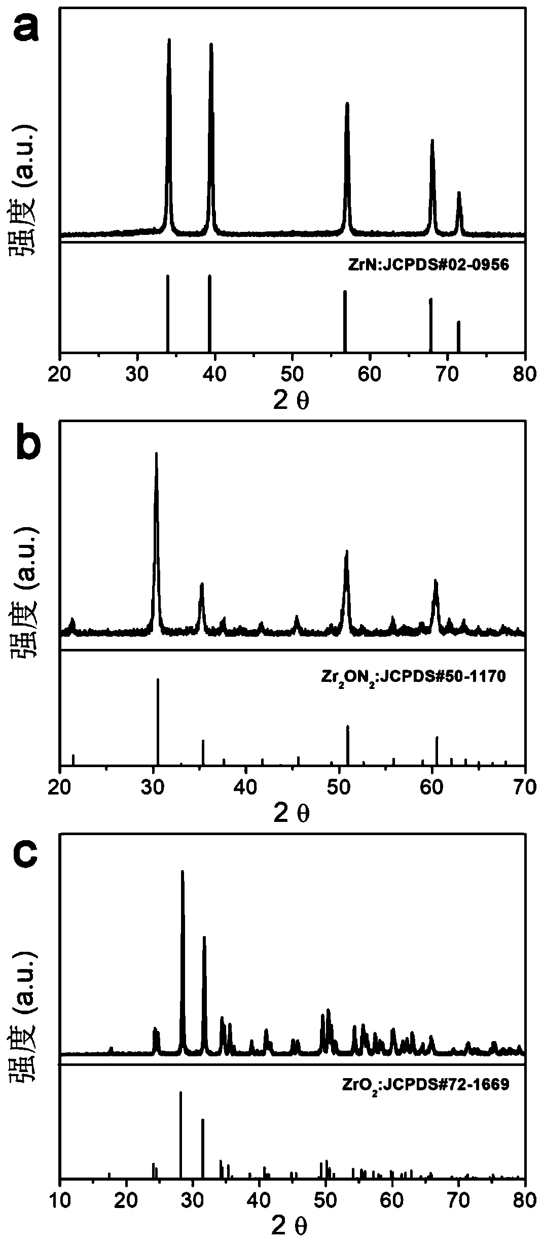
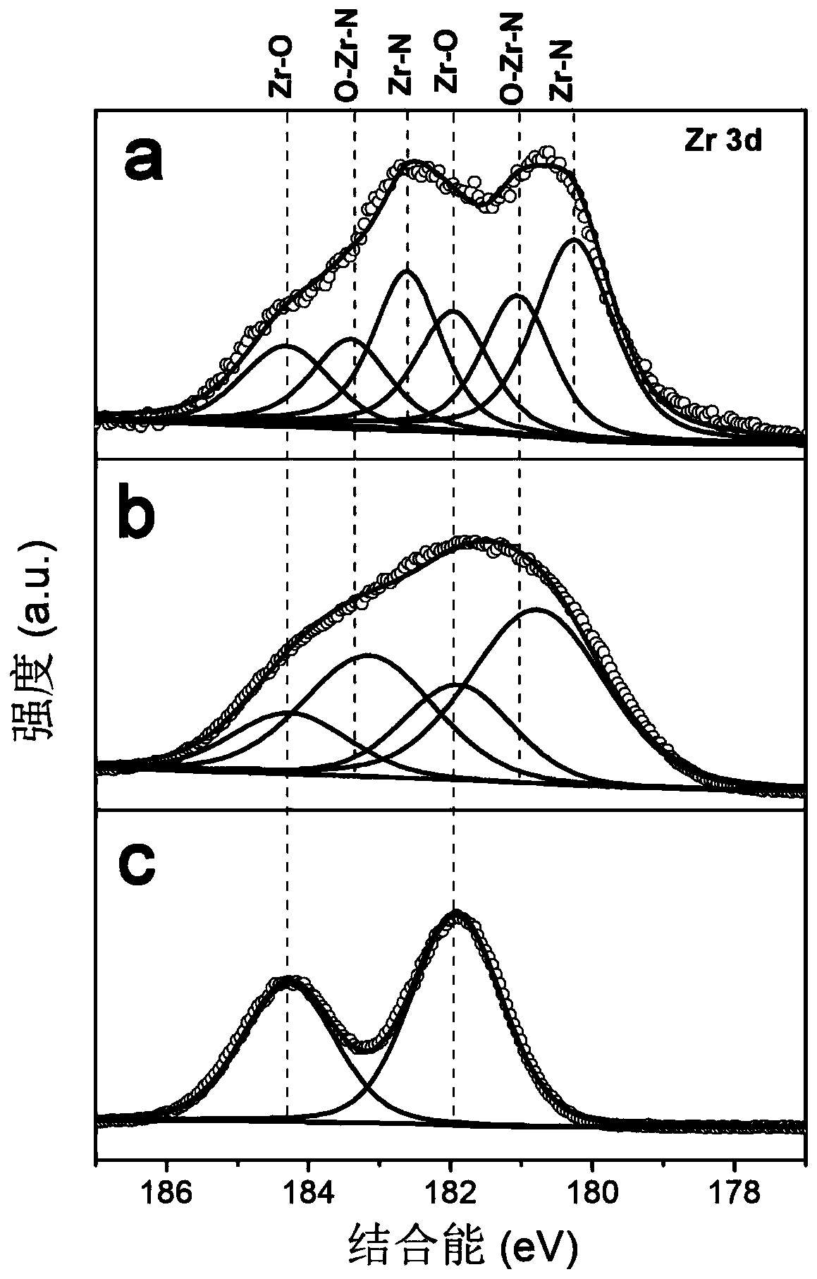
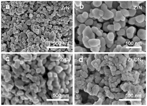
[0039] c. Put the precursor obtained in step b into a sealed tube furnace, and calcinate at 800° C. or higher for 3 hours under an argon / nitrogen atmosphere, with a heating rate of 2° C. / min. Naturally cool down to room temperature to obtain zirconium nitride (ZrN) nanoparticle catalyst. The X-ray diffraction result of the product obtained sees figure 1 , X-ray Photoelectron Spectroscopy see figure 2 , scanning electron microscope image see image 3 ;

[0040] Electrochemical performance test

[0041]Weigh 5 mg of the catalyst powder obtained by the method of the present invention, disperse it in 1 mL of isopropanol aqueous solution containing 0.05% naphtho...

Embodiment 2

[0044] Catalyst preparation

[0045] a. Dissolve 1g of anhydrous zirconium chloride in 2mL of ethanol solution to obtain a clear and transparent solution;

[0046] b. Add 3 g of urea to the solution obtained in step b, and let it stand at room temperature for more than 12 hours to obtain a colloidal precursor solution;

[0047] c. Put the precursor obtained in step b into a sealed tube furnace, and calcinate at 800° C. or higher for 3 hours under an ammonia atmosphere, with a heating rate of 2° C. / min. Naturally cool down to room temperature to obtain zirconium oxynitride nanoparticle catalyst (Zr 2 ON 2 ). The X-ray diffraction result of the product obtained sees figure 1 , X-ray Photoelectron Spectroscopy see figure 2 , scanning electron microscope image see image 3 ;

[0048] Electrochemical performance test

[0049] The test method is the same as in Example 1, except that the surface of the electrode is modified with zirconium oxynitride nanoparticles. For the po...

Embodiment 3

[0051] Catalyst preparation

[0052] a. Dissolve 1g of anhydrous zirconium chloride in 2mL of ethanol solution to obtain a clear and transparent solution;

[0053] b. Add 3 g of urea to the solution obtained in step b, and let it stand at room temperature for more than 12 hours to obtain a colloidal precursor solution;

[0054] c. Put the precursor obtained in step b in a sealed tube furnace, and calcinate at 800° C. or higher for 3 hours in an oxygen / air atmosphere, with a heating rate of 2° C. / min. Naturally lower the temperature to room temperature to obtain a zirconia nanoparticle catalyst (ZrO 2 ). The X-ray diffraction result of the product obtained sees figure 1 , X-ray Photoelectron Spectroscopy see figure 2 , scanning electron microscope image see image 3 ;

[0055] Electrochemical performance test

[0056] The test method is the same as that in Example 1, except that the electrode is modified with a zirconia nanoparticle catalyst. For details on the polariza...


PUM

PropertyMeasurementUnit
Limiting current densityaaaaaaaaaa

Abstract

The invention discloses an oxygen reduction electrocatalyst material and a preparation method thereof. The catalytic active component of the catalyst is one or more of ZrN, a ZrN composite material and a ZrN doped material; anhydrous zirconium chloride is used as a metal source, and dissolved in an absolute ethyl alcohol solution; then, a certain amount of urea is added, and after uniformly mixing, a colloidal precursor is obtained; and the obtained precursor is placed in a protective atmosphere for high-temperature roasting and nitriding, and a pure-phase zirconium nitride nanoparticle catalyst is obtained. The applicant finds that zirconium nitride, especially a cubic phase zirconium nitride material, has excellent oxygen reduction electrocatalytic performance, can replace precious metalPt in a fuel cell to serve as a cathode catalyst, and has the characteristics of low cost, high activity and high stability.

Description

technical field [0001] The invention relates to the technical field of electrocatalytic materials, in particular to an oxygen reduction electrocatalyst material and a preparation method thereof. Background technique [0002] The energy issue is one of the biggest issues in the 21st century and an important material basis for economic growth and social development. The development and utilization of renewable resources (solar energy, wind energy and tidal energy, etc.) is one of the important ways to solve the energy crisis and environmental pollution. However, the intermittent nature of these energy sources urgently requires the development of advanced energy conversion, storage technologies and devices. More and more scientific researchers have spared no effort to find sustainable energy devices, such as fuel cells, solar cells, metal-air batteries, lithium-ion batteries, supercapacitors and so on. As a new type of energy, fuel cells do not emit pollutants during operation...

Claims


Application Information

Patent Timeline
IPC IPC(8): H01M4/90H01M4/88C01G25/00B82Y30/00
CPCB82Y30/00C01G25/00H01M4/8825H01M4/90Y02E60/50
Inventor 杨明辉元瑶
Owner NINGBO INST OF MATERIALS TECH & ENG CHINESE ACADEMY OF SCI
Why Eureka
Try Eureka