Low-temperature electronic cigarette heating pipe and preparation method thereof
A heating tube and electronic cigarette technology, applied in the field of electronic cigarettes, can solve the problems of reduced energy utilization rate of heaters, reduced comfort of electronic cigarette users, poor smoking experience of smokers, etc. The effect of ironing is good, and the effect of improving the baking effect
- Summary
- Abstract
- Description
- Claims
- Application Information
AI Technical Summary
Problems solved by technology
Method used
Image
Examples
Embodiment 1
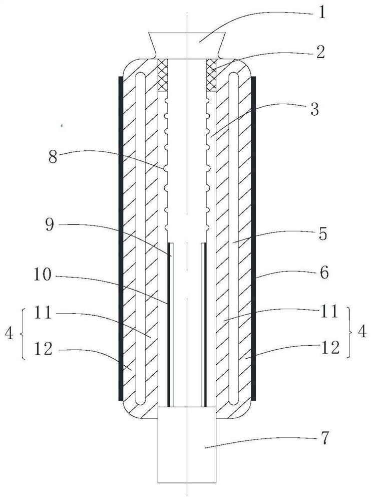
[0047] Example 1: Such as figure 1 , The present embodiment of the electronic cigarette cryogenic heat pipe comprises a heating element, heat insulating member 4, a base 7 and the tobacco inlet 1, the insulating member 4 is fixedly connected to the bottom of the base 7. The base 7 is made of insulating material, the base 7 is provided with the power supply device. Insulation material of the base 7 may be used mullite, alumina, zirconia, silica fibers and the corresponding one or more thereof.
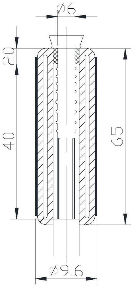
[0048] Said insulating member is a tube structure 4, insulating member 4 includes an inner wall 11 and the inner wall 11 and surrounding the inner tube wall 11 outer tube wall 12 arranged at intervals, the the inner wall 11 to form a closed cavity between the outer layer 5 and the wall 12, the radial dimension of the cavity 5 is 1mm. The insulating member of silicon oxide, mullite, preparing at least one porous alumina or a porous material is made of zirconia, and the density of the thermal...
Embodiment 2
[0052] Example 2: construction of the present embodiment is substantially the same as in Example 1, except that the heating cavity 5 radial dimension between the inner and outer wall 12 is 2mm. Thickness of the insulation seal layer 6 of 1500 microns. Heating elements below the top element 4 insulate 30mm; provided with a thermally conductive coating made of heat conductive material 9 on the heating element, the thickness of the thermally conductive coating layer 9 is 10 microns. The thermally conductive material may be an epoxy resin, a polypropylene resin, and silica gel as a substrate, doping the carbon nanotubes on a substrate, nano-carbon black, diamond powder, and graphene oxide nano-aluminum nitride, nano-silicon nitride, nano alumina, nano silica, nano-boron nitride composite of heat-transfer agent.
Embodiment 3
[0053] Example 3: configuration example and Example 2 of the present embodiment is substantially the same, except that the radial dimension of the cavity 5 between two wall heating tube of the present embodiment is 1.5mm, the inner cavity 5 of the tubular body a vacuum state. Thickness of the insulation seal layer 6 is 500 m. Heating elements below the top element 4 insulate 25mm. The thickness of thermally conductive coating 9 to 50 microns. The thickness of thermally insulating coating layer 9 is less than the thickness of the sealing layer, the thermally conductive coating 6 of 9 small thickness, better able to transfer heat generated by the heating circuit 10. Said heating element and said base away from said insulating member is provided between one end of the base insulating layer 2, Z is type embodiment of an aluminum foil of insulating material having a high reflectance and having a low thermal conductivity to the present embodiment alternately retardant cryogenic insulati...
PUM
| Property | Measurement | Unit |
|---|---|---|
| thickness | aaaaa | aaaaa |
| thickness | aaaaa | aaaaa |
| size | aaaaa | aaaaa |
Abstract
Description
Claims
Application Information
 - R&D
- Intellectual Property
- Life Sciences
- Materials
- Tech Scout
- Unparalleled Data Quality
- Higher Quality Content
- 60% Fewer Hallucinations
Browse by: Latest US Patents, China's latest patents, Technical Efficacy Thesaurus, Application Domain, Technology Topic, Popular Technical Reports.
© 2025 PatSnap. All rights reserved.Legal|Privacy policy|Modern Slavery Act Transparency Statement|Sitemap|About US| Contact US: help@patsnap.com


