
Oil sludge pyrolysis treatment device and process

A treatment device and oil sludge technology, applied in the field of oil sludge pyrolysis treatment device, can solve the problems of technical requirements for easy porcelain coking of baked dry soil, harm to human health and sustainable development, and high selectivity for high-efficiency microorganisms, so as to ensure stability. and continuous operability, preventing ceramic agglomeration, and reducing operating costs

Pending Publication Date: 2020-12-11
GUANGZHOU WEIGANG ENVIRONMENT TECH CO LTD
View PDF0 Cites 2 Cited by
  • Summary
  • Abstract
  • Description
  • Claims
  • Application Information

AI Technical Summary

Problems solved by technology

[0007] Comprehensive analysis of the above several schemes, although the first scheme has the advantages of small investment, convenience and directness, it will easily cause soil and environmental pollution around the landfill area for a long time, which will eventually seriously endanger human health and sustainable development. ; The second option has the advantages of fast processing speed, high degree of reduction, and more thorough harmlessness, but there are also problems of high processing cost, high energy consumption of the process, easy porcelain coking of the dried soil from the furnace, and high technical requirements. Disadvantages: The third scheme has the advantages of small investment, low treatment cost, and effective control of pollutant transfer, but it also has the advantages of being greatly affected by environmental factors, long treatment time, and high selectivity for high-efficiency microorganisms. Disadvantages of general application

Method used


Image

  • Oil sludge pyrolysis treatment device and process

Examples


Embodiment Construction

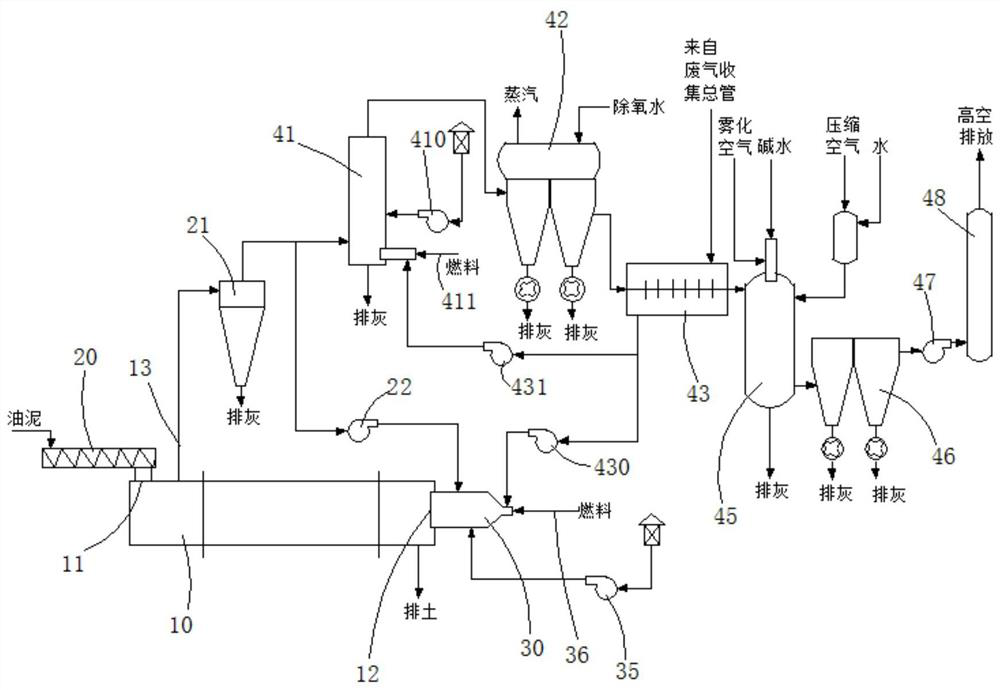
[0042] Below, in conjunction with accompanying drawing and specific embodiment, the present invention is described further:

[0043] see figure 1, is a schematic process flow diagram of a sludge pyrolysis treatment device of the present invention. The sludge pyrolysis treatment device includes a sludge pyrolysis system, a pyrolysis gas circulation system, a flue gas waste heat recovery system, and a flue gas treatment system connected in sequence. The pyrolysis system is used for pyrolysis through direct contact between hot flue gas and oil sludge; the pyrolysis gas circulation system is used to remove the ash entrained by the pyrolysis gas, and return part of the pyrolysis gas to the oil sludge pyrolysis system for recycling. utilization; the flue gas waste heat recovery system is used to burn the pyrolysis gas again, remove the flammable and harmful substances contained in the flue gas, and recycle the heat of the generated high-temperature flue gas; the flue gas treatment s...


PUM


Abstract

The invention discloses an oil sludge pyrolysis treatment device and process. The treatment device comprises an oil sludge pyrolysis system, a pyrolysis gas circulation system, a flue gas waste heat recovery system and a flue gas treatment system; the oil sludge pyrolysis system comprises a pyrolysis kiln, an oil sludge feeding screw and a combustion chamber; the pyrolysis gas circulation system comprises a cyclone separator and a high-temperature pyrolysis gas circulating fan; the high-temperature pyrolysis gas circulating fan is connected with the combustion chamber; the flue gas waste heatrecovery system comprises a burnout chamber, a waste heat boiler and an air preheater; an air outlet of the air preheater is connected with a first combustion fan and a second combustion fan; the first combustion fan is connected with the combustion chamber; the second combustion fan is connected with the burnout chamber; the flue gas treatment system comprises flue gas purification equipment andflue gas emission equipment. The oily sludge pyrolysis treatment device can effectively treat oily sludge, has the comprehensive advantages of being low in treatment cost, high in treatment degree, low in energy consumption and the like, and can reduce the content of petroleum in the oily sludge to 0.3% or below.

Description

technical field [0001] The invention relates to the technical field of oil sludge treatment, in particular to an oil sludge pyrolysis treatment device and a process thereof. Background technique [0002] Oily sludge refers to the oily solid waste produced in the process of oil extraction, transportation, refining and oily sewage treatment. The oily sludge produced by the petrochemical industry often contains a large amount of petroleum, benzene, phenols, anthracene and other toxic and harmful substances. If it is not treated in time, the stacking or landfill of oily sludge will not only occupy a large amount of arable land , and will cause serious pollution to the surrounding soil, water, and air. At the same time, in view of the fact that oily sludge has been listed as hazardous waste by the country, if it is not treated to eliminate harmful factors, it will also have a greater impact on the sustainable development of enterprises. Therefore, regardless of social and envir...

Claims


Application Information

Patent Timeline
IPC IPC(8): C02F11/10F23G7/06B01D50/00B01D53/40B01D53/78
CPCC02F11/10F23G7/06B01D53/78B01D53/40B01D50/20Y02W10/40
Inventor 夏云龙蔡珠华陈宗达
Owner GUANGZHOU WEIGANG ENVIRONMENT TECH CO LTD
Features
  • Generate Ideas
  • Intellectual Property
  • Life Sciences
  • Materials
  • Tech Scout
  • Unparalleled Data Quality
  • Higher Quality Content
  • 60% Fewer Hallucinations
Learn More