Production method of passivation contact crystalline silicon cell

A battery, hydrogen passivation technology, applied in the field of solar cells, can solve the problems of loss of solar cell conversion efficiency, photoelectric conversion efficiency loss, solar cell efficiency loss and other problems

Active Publication Date: 2021-04-20
TRINA SOLAR CO LTD
View PDF18 Cites 1 Cited by
  • Summary
  • Abstract
  • Description
  • Claims
  • Application Information

AI Technical Summary

Problems solved by technology

However, the current industry has found in practice that when a laser is used to partially melt the battery sheet along the axis of symmetry, and thermal stress or mechanical stress is used to separate the battery by scribing and splitting to cut the battery sheet, due to the Very serious laser damage is caused at the fracture surface, and there are a large number of dangling bonds and defect states on the surface, which become effective recombination centers for carriers.
A large number of carriers recombine through interface defects, which seriously reduces the conversion efficiency of solar cells
At present, for conventional PERC cells (Passivated Emitter and Rear Cell, that is, passivated emitter and rear cells), the photoelectric conversion efficiency loss of laser scribing and slicing is 0.1-0.2% compared with that before slicing.
For intrinsic thin-film heterojunction cells or N-type double-sided cells, the efficiency drop after slicing reaches 0.3-0.5%.
[0003] The industry is currently actively looking for a solution to the problem that laser cutting damage leads to the loss of efficiency of cut solar cells, which in turn reduces the power gain of half-cut modules or shingled modules, but there is no good solution

Method used


Image

  • Production method of passivation contact crystalline silicon cell
  • Production method of passivation contact crystalline silicon cell
  • Production method of passivation contact crystalline silicon cell

Examples


Embodiment Construction

[0041] The present invention will be described in detail below in conjunction with the accompanying drawings, and the features of the present invention will be further revealed in the following detailed description.

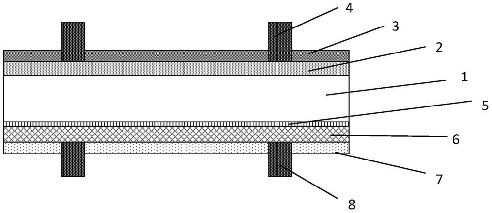
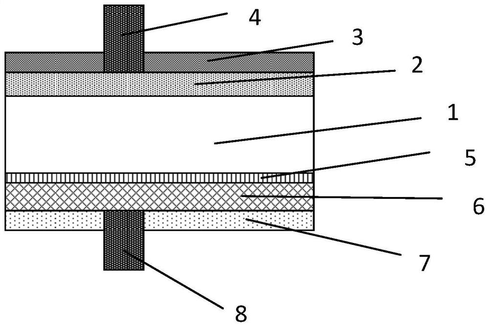
[0042] figure 1 It is a cross-sectional view of the structure of a crystalline silicon solar cell. As an example, figure 1 The crystalline silicon solar cells shown in can be n-type TOPCon cells or POLO solar cells, and the cross-sectional view of a typical cell structure is shown in figure 1 As shown, it includes an N-type silicon wafer 1, a boron diffused emitter 2, a front anti-reflection film 3, a front electrode 4, a tunnel oxide layer 5, a phosphorus-doped polysilicon film 6, a back SiNx:H film 7, and a back electrode 8 .

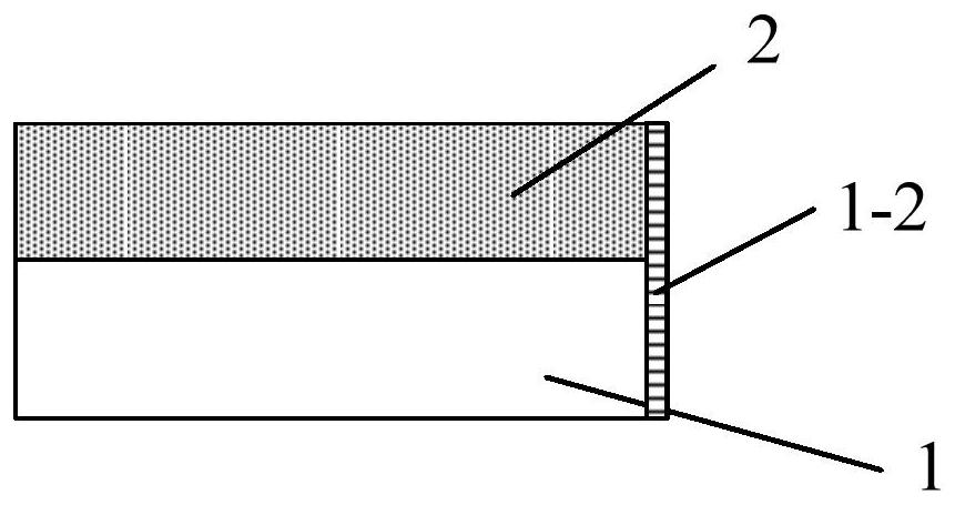
[0043] Assuming that the battery is laser cut and it is a half battery, its cross-section is as follows figure 2 shown. As mentioned in the background section, damage due to conventional laser cutting will be figure 2 The edge in...


PUM


Abstract

The invention provides a production method of a passivation contact crystalline silicon cell. The method comprises the following steps: scribing and cracking a solar cell by a laser to obtain a plurality of cell slices; coating a passivation slurry on a cutting edge of each battery slice; and carrying out hydrogen passivation on the battery slice coated with the passivation slurry, wherein the passivation slurry can be sintered in a hydrogen passivation process.

Description

technical field [0001] The invention relates to the field of solar cells, in particular to a method for preparing a passivated contact crystal silicon cell. Background technique [0002] At present, due to the popularization of slicing battery components, shingling technology, merging and splicing technology, the use of laser to cut the whole battery cell has gradually become the mainstream trend of the industry. Especially for the promotion and application of large silicon wafers, cutting the whole cell into 1 / 2, 1 / 3, ..., 1 / n to reduce the series resistance of the module is the only way to increase the output power of the solar cell module. However, the current industry has found in practice that when a laser is used to partially melt the battery sheet along the axis of symmetry, and thermal stress or mechanical stress is used to separate the battery by scribing and splitting to cut the battery sheet, due to the Very serious laser damage is caused at the fracture surface,...

Claims


Application Information

Patent Timeline
Patent Type & Authority Applications(China)
IPC IPC(8): H01L31/18B07C3/12
CPCY02P70/50
Inventor 王尧陈达明陈奕峰刘成法邹杨
Owner TRINA SOLAR CO LTD
Why Eureka
Try Eureka