Method and device for recovering oil and gas

An oil-gas and gas-phase technology, which is used in the recovery of liquid hydrocarbon mixtures, the treatment of hydrocarbon oil, and the petroleum industry. , the effect of efficient separation and recovery

Active Publication Date: 2022-04-15
SINOPEC ENG +1
View PDF5 Cites 0 Cited by
  • Summary
  • Abstract
  • Description
  • Claims
  • Application Information

AI Technical Summary

Problems solved by technology

[0005] (2) The absorption and stabilization system uses stable gasoline as an absorbent to recover liquefied gas components. Due to the high yield of liquefied gas components in the catalytic cracking process, gasoline is Gasoline absorbing tower, ethane deabsorbing tower and stabilizing tower are circulated, and the circulation volume is large, the temperature at the bottom of ethane desorbing tower and stabilizing tower is high, the heat load of reboiler at the bottom of the tower is relatively large, and the energy consumption is low high
[0006] (3) The entire technological process is relatively long, which increases investment and energy consumption accordingly
[0007] (4) When the recovered C2 product is sent to the separation unit of the ethylene plant, some of the heavy components such as propylene contained in the C2 product can be recovered through the ethylene separation unit; but when the recovered C2 product is sent to the downstream production of ethylbenzene , the propylene component contained in it will bring many adverse effects to the production of ethylbenzene, which will not only greatly increase the consumption of benzene, but also directly affect the quality of ethylbenzene and styrene products
Due to the low boiling point of the carbon 2 component, the separation of the carbon 2 and carbon 3 components usually requires a temperature of -5 to -20°C. For this reason, dehydration and CO removal are required 2 processing, and requires a lower temperature grade of refrigerant, the investment and energy consumption are large
[0008] (5) The existing process desulfurizes and sweetens the dry gas and liquefied gas after absorption and stabilization, H 2 S and mercaptans circulate in the entire absorption stabilization system, which may cause related corrosion problems, and there is H in the entire absorption stabilization system. 2 Possible security issues caused by S leakage

Method used


Image

  • Method and device for recovering oil and gas
  • Method and device for recovering oil and gas
  • Method and device for recovering oil and gas

Examples


Embodiment 1

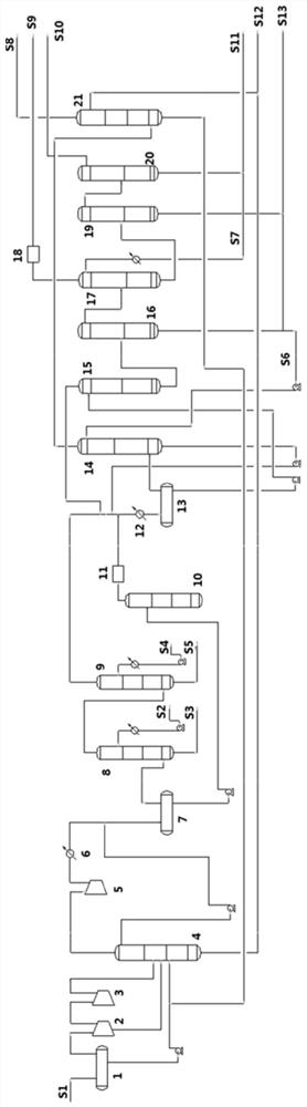
[0107] Oil and gas recovery devices include:

[0108] Oil and gas feed pipeline, gas-liquid separation tank I1, compressor I, debutanizer 4, compressor II 5, cooler Ⅰ6, gas-liquid separation tank Ⅱ7, gas-rich desulfurization tower 8, gas-rich alkali washing tower 9, liquid Hydrocarbon desulfurization tower 10, liquid hydrocarbon sweetening reactor 11, cooler II 12, feed tank 13, absorption tower 14, demethanizer 15, depropanizer I 16, deethanizer 17, impurity treatment unit 18, depropanizer Ⅱ19, propylene rectification tower 20, absorbent recovery tower 21;

[0109] Wherein, the oil-gas feed line is connected to the inlet of the gas-liquid separation tank I1, the top of the gas-liquid separation tank I1 is connected to the compressor 1 and the debutanizer 4 in turn, and the bottom of the tank is connected to the debutanizer 4;

[0110] There is a reflux tank on the top of the debutanizer 4, the top of the reflux tank is connected to the compressor II 5, the cooler Ⅰ6 and the ...

Embodiment 2

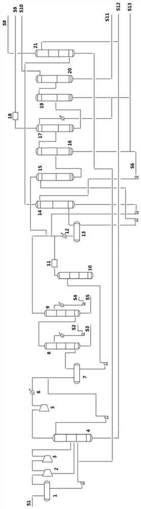
[0146] use as figure 2 The shown process flow reclaims oil and gas, and the difference from Example 1 is that in the separation step, demethanization: the liquid phase from the bottom of the feed tank 13 removes methane in the demethanizer 15, and simultaneously removes Remove a small part of C2 and components above C2, the gas phase at the top of the demethanizer 15 is cooled and then returned to the feed tank 13, and the liquid phase at the bottom of the tower is sent to the depropanizer I16;

[0147] Depropanization I: The liquid phase components from the bottom of the demethanizer 15 are separated in the depropanizer I16, and the separated top gas phase is sent to the deethanizer 17, and at least part of the bottom liquid phase is used as a mixed C4 The absorbent is sent to the absorption tower 14, and the remainder is extracted as the C4 product S13;

[0148] Deethanization: The gas phase from the top of the depropanizer I16 is separated from the C2 component in the dee...

Embodiment 3

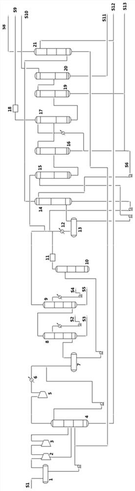
[0157] use as image 3 The shown process flow reclaims oil and gas, and the difference from Example 1 is that in the separation step, demethanization: the liquid phase from the bottom of the feed tank 13 removes methane in the demethanizer 15, and simultaneously removes Remove a small part of C2 and components above C2, the gas phase at the top of the demethanizer 15 is cooled and then returned to the feed tank 13, and the liquid phase at the bottom of the tower is sent to the depropanizer I16;

[0158] Depropanization I: The liquid phase components from the bottom of the demethanizer 15 are separated in the depropanizer I16, and the separated top gas phase is sent to the deethanizer 17, and at least part of the bottom liquid phase is used as a mixed C4 The absorbent is sent to the absorption tower 14, and a part is sent to the deethanizer 17 as a mixed C4 absorbent after cooling, and the remaining part is extracted as a C4 product S13;

[0159] Deethanization: The gas phase ...


PUM


Abstract

The invention belongs to the field of chemical industry, and specifically discloses a method and device for recovering oil and gas. The method has simple process flow, mild operating conditions, less cooling capacity consumption, and can realize the recovery of gasoline, carbon 2, carbon 3 and carbon Efficient separation and recovery of four components, especially the efficient separation and recovery of carbon two, carbon three and carbon four components; and the present invention uses gas phase and liquid phase to desulfurize and sweeten alcohol respectively, and the gas phase is desulfurized and sweetened under high pressure. The volume of the equipment is small, the investment is low, and the desulfurization effect is good.

Description

technical field [0001] The invention belongs to the field of oil refining and chemical industry, and more specifically relates to a method and device for recovering oil and gas, and more specifically relates to a device and device for recovering oil and gas in processes with high gas yields such as catalytic cracking, catalytic cracking and delayed coking. method. Background technique [0002] Light hydrocarbons refer to components such as methane, ethane, ethylene, propane, propylene, and C4 obtained from petrochemical processes. The separation process of light hydrocarbons has always been the focus of petrochemical processes. Among them, the separation process between carbon 2, carbon 3 and carbon 4 is relatively mature, and rectification is usually used. Due to the low boiling point of methane, if distillation is used to separate methane and carbon dioxide, it needs to be cooled to -100°C or lower, that is, cryogenic separation, which is usually used in ethylene plants, ...

Claims


Application Information

Patent Timeline
Patent Type & Authority Patents(China)
IPC IPC(8): C10G5/04C10G5/06C10G7/00C10G53/00
CPCC10G5/04C10G5/06C10G53/00C10G7/00C10G2300/202C10G2300/207C10G2400/02C10G2400/20
Inventor 黄孟旗余龙红吴雷江盛阳丁昱文吴迪
Owner SINOPEC ENG
Why Eureka
Try Eureka