
Photocuring micro-fluidic chip based on elastic support body and preparation method and application thereof

A microfluidic chip and elastic support technology, applied in chemical instruments and methods, laboratory containers, laboratory utensils, etc., can solve chip cutting, punching, inconvenient connection of external pipelines, increasing equipment, processing technology Complexity and cost, poor flexibility of light-cured materials, etc., to achieve the effect of easy connection of external pipelines, good potential for mass production, and the elimination of PDMS mold processing links

Active Publication Date: 2021-06-04
ZHEJIANG UNIV
View PDF15 Cites 6 Cited by
  • Summary
  • Abstract
  • Description
  • Claims
  • Application Information

AI Technical Summary

Problems solved by technology

[0005] But so far, the processing of light-cured microfluidic chips still faces many challenges: 1) Many light-cured materials have poor flexibility, and it is difficult to mold them from hard molds such as silicon, so only elastic PDMS and other materials can be used as molds , which not only increases the processing steps, but also is not suitable for photocurable materials that can swell PDMS
2) Due to the problem of oxygen inhibition, the current light-cured microfluidic chip processing is mostly completed in a vacuum or nitrogen environment, which greatly increases the complexity and cost of equipment and processing technology, which is especially prominent when using PDMS materials as molds
3) Most photocurable materials are not suitable as the main body of microfluidic chips alone (generally a few millimeters thick)
On the one hand, this is because they generally have a strong absorption of ultraviolet light, which causes differences in the polymerization reaction along the direction of light propagation. In addition, the rapid and large amount of heat release is also likely to cause unevenness inside the material; on the other hand, the mechanical properties of many photocurable materials The performance does not meet the requirements of microfluidic chips (such as too soft, too hard or fragile, etc.), and it also makes the chip inconvenient in terms of cutting, drilling, and external pipeline connections.

Method used


Image

  • Photocuring micro-fluidic chip based on elastic support body and preparation method and application thereof
  • Photocuring micro-fluidic chip based on elastic support body and preparation method and application thereof
  • Photocuring micro-fluidic chip based on elastic support body and preparation method and application thereof

Examples


Embodiment 1

[0099] Example 1 Preparation of elastic support based on thiol-ene material:

[0100] a) Preparation solution: by mass percentage, 73% tetrakis (2-mercaptoacetic acid) pentaerythritol ester (Aladdin, P160529), 26% 1,3,5-triallyl-1,3,5- Triazine-2,4,6(1H,3H,5H)-trione (Aladdin, T123406), 1% photoinitiator 2,4,6-trimethylbenzoylphenylphosphonic acid ethyl ester ( Aladdin, E186856) mixed well to obtain solution 1.

[0101] b) Pour the solution 1 prepared in step a) into and fill the groove with a depth of 3mm, cover it with a piece of clean glass and flatten it, and apply ultraviolet light (365nm, 2.5mW / cm 2 ), the irradiation time is 180s~200s.

[0102] c) After solidification, the thiol-ene solid is removed from the groove for later use.

[0103] The thiol-ene solid (bulk layer) obtained in this example has good elasticity and has a photocurable functional group itself, which can be directly used as an elastic support.

Embodiment 2

[0104] Embodiment 2 Preparation of elastic support based on polyurethane acrylate material:

[0105] a) Prepared solution: by mass percentage, 99% polyurethane acrylate (Changxing material company, 6115J-80), 1% photoinitiator 2-hydroxyl-2-methyl-1-phenyl-1-acetone (Sigma, 405655) and mix well to obtain solution 2.

[0106] b) Pour the solution 2 prepared in step a) into the groove with a depth of 3mm, cover it with a piece of clean glass and flatten it, and apply ultraviolet light (365nm, 2.5mW / cm 2 ), the irradiation time is 340s~360s.

[0107] c) After curing, take out the polyurethane acrylate solid from the groove for later use.

[0108] The urethane acrylate solid (body layer) obtained in this embodiment has good elasticity, and has photocurable functional groups itself, and can be directly used as an elastic support.

Embodiment 3

[0109] Embodiment 3 PDMS surface modification acrylate functional group as elastic support body:

[0110] a) Mix PDMS prepolymer (Momentive, RTV615) and curing agent (Dow Corning, Sylgard184) at a mass ratio of 10:1, stir evenly, pour 30g into the injection tank, and heat and cure the whole for 2 hours.

[0111] b) After the thermally cured PDMS is subjected to plasma treatment (500V, 13.56MHz, 45s), it is immersed in a silane coupling agent solution (3-(methacryloyloxy)propyltrimethoxysilane ethanol solution, volume fraction 10%), soak for 1 to 2 hours to ensure that the PDMS surface is modified with acrylate functional groups.

[0112] c) The PDMS in step b) was taken out, rinsed with ethanol, and dried with nitrogen gas for later use.

[0113] In this embodiment, the surface of the PDMS bulk layer is modified with photocurable functional groups and used as an elastic support.


PUM

PropertyMeasurementUnit
thicknessaaaaaaaaaa
thicknessaaaaaaaaaa
elastic modulusaaaaaaaaaa

Abstract

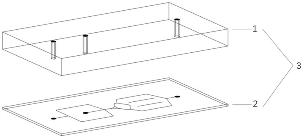
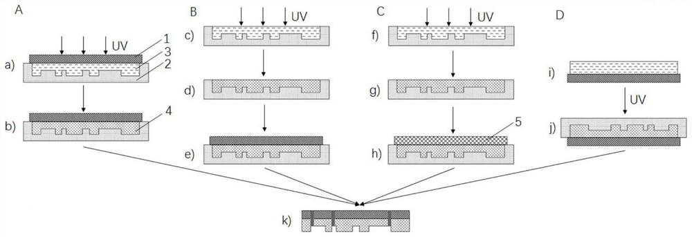
The invention discloses a photocuring micro-fluidic chip based on an elastic support body and a preparation method and application thereof, the photocuring micro-fluidic chip comprises a channel structure layer and a sealing layer, the channel structure layer comprises a photocuring layer containing a channel structure and an elastic support body used for supporting the photocuring layer; the elastic support body and the photocuring layer are connected through covalent bonding or adhesion; the photocuring layer containing the channel structure is formed by covering a mold with a photocuring raw material and curing after light irradiation; the elastic support body comprises a body layer and a selectively added connecting layer. The photocuring micro-fluidic chip has no special limitation on photocuring materials and mold types so that the whole chip processing process can be carried out at room temperature in an atmospheric environment; in addition, punching, sealing, cutting, external pipeline connection and the like of the chip are simpler, more convenient and quicker, so that the chip is suitable for carrying out design and development of a micro-fluidic chip prototype in a conventional laboratory, and also has good batch production potential.

Description

technical field [0001] The invention relates to the technical field of microfluidic chips, in particular to a light-cured microfluidic chip based on an elastic support, a preparation method and application thereof. Background technique [0002] Due to the advantages of precise fluid control, less sample demand, fast response, and easy integration, microfluidic chips have gained more and more extensive research and application in the fields of chemistry, biology, and medicine. At present, the materials used to prepare microfluidic chips mainly include silicon, glass and organic polymers. Among them, organic polymers have many advantages over inorganic materials such as silicon and glass, including various types, easy to obtain large aspect ratios, mass production, and low cost. Representative organic polymers include polycarbonate (PC), polymethylmethacrylate (PMMA), cycloolefin copolymer (COC), and the like. These materials can produce microfluidic chips in batches and at ...

Claims


Application Information

Patent Timeline
Patent Type & Authority Applications(China)
IPC IPC(8): B01L3/00C08G75/045C08F299/06C08F2/48C08G77/38C08F222/20C08F220/40C08J5/18C08L35/02
CPCB01L3/502707C08G75/045C08F299/065C08F2/48C08G77/38C08F222/102C08J5/18C08J2335/02C08F220/40
Inventor 张涛何宇祝芙天纯
Owner ZHEJIANG UNIV
Learn More