A hydrogen shaft furnace ironmaking system and method using electric energy heating

A hydrogen and shaft furnace technology, applied in the field of metallurgy, can solve the problems of insufficient hydrogen shaft furnace, insufficient physical energy, power consumption and heat loss, etc., and achieve the effects of saving equipment operating costs, improving energy utilization, and reducing process energy consumption

Active Publication Date: 2022-02-11
NORTHEASTERN UNIV LIAONING
View PDF13 Cites 0 Cited by
  • Summary
  • Abstract
  • Description
  • Claims
  • Application Information

AI Technical Summary

Problems solved by technology

[0003] For the iron and steel industry, the electric furnace is a very mature technical equipment, so the hydrogen shaft furnace is the current research focus; the current outstanding problem of the hydrogen shaft furnace is that the physical energy (ie heat) is insufficient and the chemical energy is seriously excessive; this is because, relatively than CO, H 2 The reduction of iron oxide is a strong endothermic reaction, and the injected H 2 If the amount is small, the heat in the hydrogen shaft furnace will be insufficient, so it is difficult to maintain the temperature required for reduction and the predetermined production rate; if the predetermined production requirements are to be met, the H 2 amount; this will inevitably lead to H in the hydrogen shaft furnace top gas 2 The utilization rate is very low (up to about 25%), that is, there is a serious excess of chemical energy
[0004] Under the premise of dehydration recycling of furnace top gas (as the technical method proposed by patent CN109913606A and CN111440914A), the H of the hydrogen shaft furnace 2 The utilization rate can reach 100% in theory; although it seems that there is no problem of excess chemical energy in the hydrogen shaft furnace, the total amount of gas entering the furnace is still too much, which will make the circulating gas excessive, which will lead to unnecessary The power consumption and the inevitable heat loss for dehydration and cooling; therefore, trying to maintain the temperature in the furnace, thereby reducing the amount of circulating gas has become an urgent problem to be solved in the hydrogen shaft furnace; in the upper part of the furnace, oxygen (O 2 ) combustion part H 2 , the conversion of chemical energy into thermal energy can maintain the temperature in the furnace
The hydrogen shaft furnace process being developed by Midrex has actually taken this into consideration; however, it should be pointed out that the H 2 It is obtained by consuming electric energy. Compared with directly heating the charge with electric energy, H 2 Combusting it to release heat not only has the problem of looking far away, but more importantly, it is very likely that the local oxidizing atmosphere in the furnace will be too high and affect the reduction of the charge; in this way, directly using electric energy to heat the charge becomes a An important, if not the only, option for supplying heat to the hydrogen shaft furnace
[0005] At present, the technology of electric energy heating charge mainly includes microwave heating and induction heating; microwave heating has been widely used in the field of ironmaking. However, in addition to iron-containing materials, the raw materials of microwave heating furnaces generally require coal powder / block, a typical fossil energy source, which is obviously in line with the original intention of promoting hydrogen shaft furnaces to greatly reduce carbon emissions in the steel industry On the other hand, if the coal with strong microwave absorption ability is not introduced, but H is injected into the kiln 2 , there will be a problem that the microwave absorption capacity of the iron-containing material is reduced to direct reduced iron with a high metallization rate, which will lead to a sudden drop in microwave heating efficiency.
In terms of induction heating, the patent CN109913606A discloses a coal-to-hydrogen shaft furnace ironmaking system and process, and the furnace charge involved in the induction heating shaft furnace is only oxidized pellets; since iron oxides cannot achieve self-induction heating, the patent requires Inductive heating of the protected upper charge is actually difficult to achieve; although the patent has pointed out that the induction lining can be used as a heating body, this has the problem that only the surface of the material column is heated, so the effect is poor
In addition, the currently published related patents (such as patent CN109913606A and patent CN111440914A, etc.) all involve adding H 2 Preheat to about 900°C, and then send it into the high temperature H in the furnace 2 into the furnace method; doing so either by heating H 2 The equipment still conveys H 2 The pipeline, due to the high temperature H 2 High permeability to metals, both prone to pipe material failure and H 2 Diffusion leakage, there is a big security risk
[0006] To sum up, in order to maintain the temperature in the hydrogen shaft furnace and reduce its circulating gas volume, the electric hydrogen metallurgy concept of "electric heating-gas reduction" has been preliminarily formed at this stage. Due to some insurmountable disadvantages or defects, the published Related technical methods are still largely uneconomical and have potential safety hazards in the further engineering practice of hydrogen shaft furnaces

Method used


Image

  • A hydrogen shaft furnace ironmaking system and method using electric energy heating
  • A hydrogen shaft furnace ironmaking system and method using electric energy heating

Examples


Embodiment 1

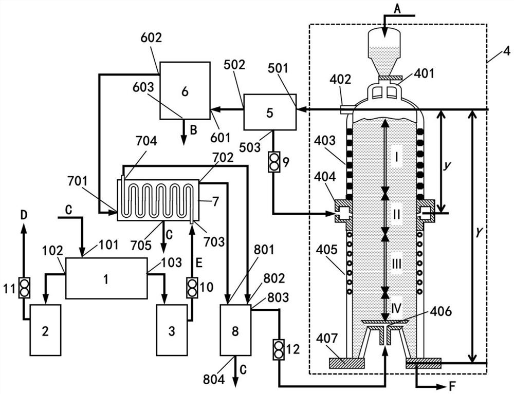
[0066] The structure of the hydrogen shaft furnace ironmaking system heated by electric energy is as follows: figure 1 As shown, it includes water electrolyzer 1, hydrogen storage tank 3, electric energy heating hydrogen shaft furnace 4, heat exchanger 7, gas mixing tank 8;

[0067]The cover of the furnace body of the electric energy heating hydrogen shaft furnace 4 is provided with a feed port to communicate with the feeder 401, and the feed port of the feeder 401 is communicated with the discharge port of the feed bin; the bottom of the cover of the furnace body is successively Microwave heating section I, middle section II, induction heating section III, cooling section IV and screw discharger 407, tail gas outlet 402 is provided on the head, microwave radiation source 403 is installed on the side wall of microwave heating section I, middle section The side wall of II is provided with an air inlet pipe 404, and the side wall of the furnace body inside the air inlet pipe 404...

Embodiment 2

[0091] The structure of the hydrogen shaft furnace ironmaking system using electric energy heating is the same as in Example 1;

[0092] Method is with embodiment 1, and difference is:

[0093] (1) The iron-containing material A is a pellet material with a particle size of 9 mm;

[0094] (2) Control the temperature in microwave heating section I to 700°C, and the temperature in induction heating section III to 880°C;

[0095] (3) control split tail gas to account for 20% of the total volume of tail gas;

[0096] (4) The metallization ratio of direct reduced iron F is 98.4%.

Embodiment 3

[0098] The structure of the hydrogen shaft furnace ironmaking system using electric energy heating is the same as in Example 1;

[0099] Method is with embodiment 1, and difference is:

[0100] (1) The iron-containing material A is a pellet material with a particle size of 10mm;

[0101] (2) Control the temperature in microwave heating section I to 800°C, and the temperature in induction heating section III to 920°C;

[0102] (3) control split tail gas to account for 30% of the total volume of tail gas;

[0103] (4) The metallization ratio of direct reduced iron F is 98.5%.


PUM

PropertyMeasurementUnit
particle diameteraaaaaaaaaa

Abstract

A hydrogen shaft furnace ironmaking system and method using electric energy heating, the system includes a water electrolyzer, a hydrogen storage tank, an electric energy heating hydrogen shaft furnace, a heat exchanger, and a gas mixing tank; the furnace body is provided with a microwave heating section, a middle section, The induction heating section, the cooling section and the screw discharger, the air inlet pier is below the cooling section, and the water electrolyzer, hydrogen storage tank, heat exchanger, gas mixing tank are connected with the air inlet of the air inlet pier in sequence. The method is as follows: (1) The hydrogen gas generated by the electrolysis of the water electrolyzer is passed into the hydrogen storage tank; (2) The hydrogen gas is passed into the coil in the heat exchanger, discharged into the gas mixing tank, and passed into the furnace body through the air inlet pier; (3) Turn on the microwave radiation source and the induction coil; (4) Put the iron-containing material into the furnace body to exchange heat with the gas and undergo a reduction reaction; (5) After the iron-containing material passes through each section of the furnace body, it will generate direct reduced iron and discharge it. The method of the present invention avoids oxygen blowing at the upper part, can realize the direct recovery and utilization of part of the high-temperature tail gas on the top of the furnace, reduces energy consumption and operation cost, and can avoid pipeline material failure and other related safety accidents caused by hydrogen diffusion.

Description

technical field [0001] The invention belongs to the technical field of metallurgy, and in particular relates to a hydrogen shaft furnace ironmaking system and method using electric energy heating. Background technique [0002] At present, the iron and steel production process mainly involves two kinds of blast furnace-converter long process and shaft furnace-electric furnace short process, but the former is the main one. However, due to its own characteristics, the ironmaking blast furnace cannot get rid of its dependence on high-quality metallurgical coke, so the development potential of low-carbon transformation around the blast furnace-converter long process is limited. The short process of shaft furnace and electric furnace is different. At present, shaft furnaces producing direct reduced iron mostly use carbon monoxide (CO) and hydrogen (H 2 ) mixed gas as a reducing medium. Inexpensive, large-scale production of H using clean energy sources for the foreseeable future...

Claims


Application Information

Patent Timeline
Patent Type & Authority Patents(China)
IPC IPC(8): C21B13/02
CPCC21B13/02C21B13/0073C21B2100/66C21B2100/44Y02P10/134
Inventor 邵磊付莹雪张晓楠赵晨曦王全乐曲迎霞邹宗树李明明
Owner NORTHEASTERN UNIV LIAONING
Why Eureka
Try Eureka