Wireless electric energy transmission device for improving system interoperability and control method

A technology of wireless power transmission and interoperability, applied in the direction of circuit devices, battery circuit devices, power management, etc., can solve problems such as circuit detuning, low transmission efficiency, and affecting transmission efficiency, so as to reduce installation space and avoid components Damage, effect of reducing system cost

Active Publication Date: 2021-06-18
NANJING UNIV OF AERONAUTICS & ASTRONAUTICS +1
View PDF3 Cites 8 Cited by
  • Summary
  • Abstract
  • Description
  • Claims
  • Application Information

AI Technical Summary

Problems solved by technology

attached image 3 The technical solution shown introduces a first-stage Buck converter on the ground side to adjust the DC bus voltage, and replaces the two lower tubes of the uncontrolled rectifier bridge on the vehicle side with MOS tubes, and directly adjusts the output by controlling the conduction angle of the MOS tubes. Gain to achieve fast dynamic response to the output. Compared with the dynamic tuning scheme, its control complexity is greatly reduced, but the additional introduction of a DC / DC converter also increases the size and cost of the system
In addition, the controllable rectification circuit will also change the equivalent load properties of the resonant unit, introduce additional capacitive or inductive reactance, cause circuit detuning, and affect transmission efficiency
In order to be compatible with low-power transmission requirements and light-load conditions, usually the adjustment depth of the controllable rectification needs to be very deep, resulting in a high degree of system detuning and low transmission efficiency

Method used


Image

  • Wireless electric energy transmission device for improving system interoperability and control method
  • Wireless electric energy transmission device for improving system interoperability and control method
  • Wireless electric energy transmission device for improving system interoperability and control method

Examples


Embodiment 1

[0098] Embodiment one: device embodiment:

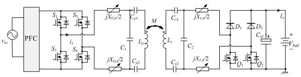
[0099] Figure 4 It is a schematic structural diagram of the power transmission device for improving the interoperability of the IPT system according to the present invention. like Figure 4 As shown, the power transmission device for improving the interoperability of the IPT system in the present invention includes a power factor correction circuit 101, an inverter circuit 102, a resonant unit 103, a rectifier circuit 104, a filter circuit 105, and a load 106 cascaded in sequence, and also includes a source side regulators, inverter mode controllers, and load-side regulators.

[0100] Wherein: the power factor correction circuit is a single-phase and three-phase compatible AC / DC circuit, which is used to receive the alternating current provided by the power grid 100, and convert it into direct current, and output it to the inverter circuit; the inverter circuit is composed of the first bridge arm and The second bridge arm is conn...

Embodiment 2

[0103] Embodiment 2: Power Factor Correction Circuit and Source-side Regulator

[0104] In the present invention, the power factor correction circuit 101 is a single-phase and three-phase compatible AC / DC circuit. Figure 5 A preferred single-phase three-phase compatible AC / DC circuit diagram is shown, including a switching module 101a, a compatible module 101b and a power module 101c cascaded in sequence.

[0105] like Figure 5 As shown, the switch module 101a includes three AC input ports, one ground input port, three switches K a * , K b * , K c *, and three AC output ports, wherein the heads of the three switches are respectively connected to the three AC input ports, the tail ends of the three switches are respectively connected to the three AC output ports, and the three switches are respectively connected to the three AC output ports. switch K a * , K b * , K c * Controlled by the source-side regulator, when the switching module 101a is connected to ...

Embodiment 3

[0109] Embodiment 3: inverter circuit and inverter mode controller

[0110] Figure 9 , Figure 10 The equivalent circuit diagrams of the inverter circuit in the double-bridge operating mode and the single-bridge operating mode are given respectively. The inverter circuit is controlled by the inverter mode controller. Since both the inverter mode controller and the source-side controller are located on the primary side of the non-contact transformer, the inverter mode controller and the source-side controller can share a digital control chip . The inverter mode controller provides power tubes in the inverter circuit S 1 , S 2 , S 3 , S 4 drive signal, where S 1 and S 2 Complementary conduction, S 3 and S 4 Complementary conduction. When the inverter circuit works in the double bridge arm mode, the output of the inverter circuit v 1 is high for V bus 、 Low level is - V bus The square wave signal of the square wave, based on Fourier decomposition, the o...


PUM


Abstract

The invention discloses a wireless electric energy transmission device for improving system interoperability and a control method. The device comprises a power factor correction circuit, an inverter circuit, a resonance unit, a rectification circuit, a filter circuit and a load which are sequentially cascaded, and also comprises a source side regulator, an inverter mode controller and a load side regulator. By switching the working modes of the inverter circuit and the rectifying circuit, with a bus voltage regulation and controllable rectifying technology, interoperation and high-efficiency electric energy transmission of the IPT system are realized, and multi-gear power level transmission requirements can be met in a wide load range and a wide coupling coefficient range. According to the invention, the interoperation requirements of three types of power levels and three types of energy transfer distances of EV WPT system vehicle-mounted end equipment are met by using one set of device, additional circuit elements do not need to be added in the aspect of circuit topology, the system cost and the installation space are effectively reduced, and the cost performance is high.

Description

technical field [0001] The invention relates to a power transmission device and a control method for improving the interoperability of an IPT system, and belongs to the technical field of wireless charging. Background technique [0002] With the gradual depletion of global fossil energy and the increasingly serious environmental pollution, electric vehicles (EV) have attracted widespread attention due to their advantages of high energy utilization rate, environmental protection and cleanness, and various types of available energy, and have been vigorously promoted by countries all over the world. The market is commercially available. Compared with contact wired charging, Wireless Power Transfer (WPT) has the advantages of convenience, safety, beauty, and high degree of automation. It is easy to realize unmanned automatic charging and distributed intermittent power supply, and extend the continuous driving of electric vehicles. It is expected to seamlessly connect with unman...

Claims


Application Information

Patent Timeline
Patent Type & Authority Applications(China)
IPC IPC(8): H02J50/12H02J7/02H02J7/10B60L53/12
CPCB60L53/12H02J7/02H02J7/06H02J50/12H02J2207/20Y02T10/70Y02T10/7072Y02T10/72Y02T90/14Y02T90/16
Inventor 陈乾宏柯光洁张帅张斌徐立刚温振霖任小永张之梁
Owner NANJING UNIV OF AERONAUTICS & ASTRONAUTICS
Why Eureka
Try Eureka