
Manufacturing method of high-strength wear-resistant corrosion-resistant contact

A manufacturing method and anti-corrosion technology, applied in the direction of electrical components, circuits, electric switches, etc., can solve problems such as environmental pollution, achieve the effects of improving strength and corrosion resistance, reducing rapid wear, and controlling the cost of contacts

Active Publication Date: 2022-01-28
清研特材科技(洛阳)有限公司 +1
View PDF9 Cites 0 Cited by
  • Summary
  • Abstract
  • Description
  • Claims
  • Application Information

AI Technical Summary

Problems solved by technology

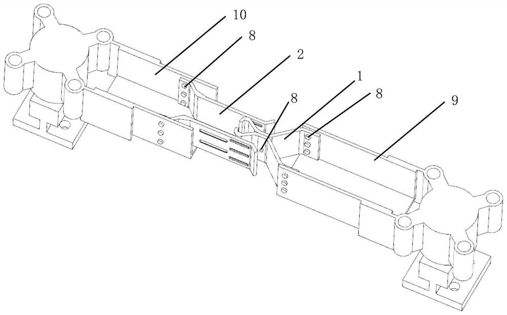
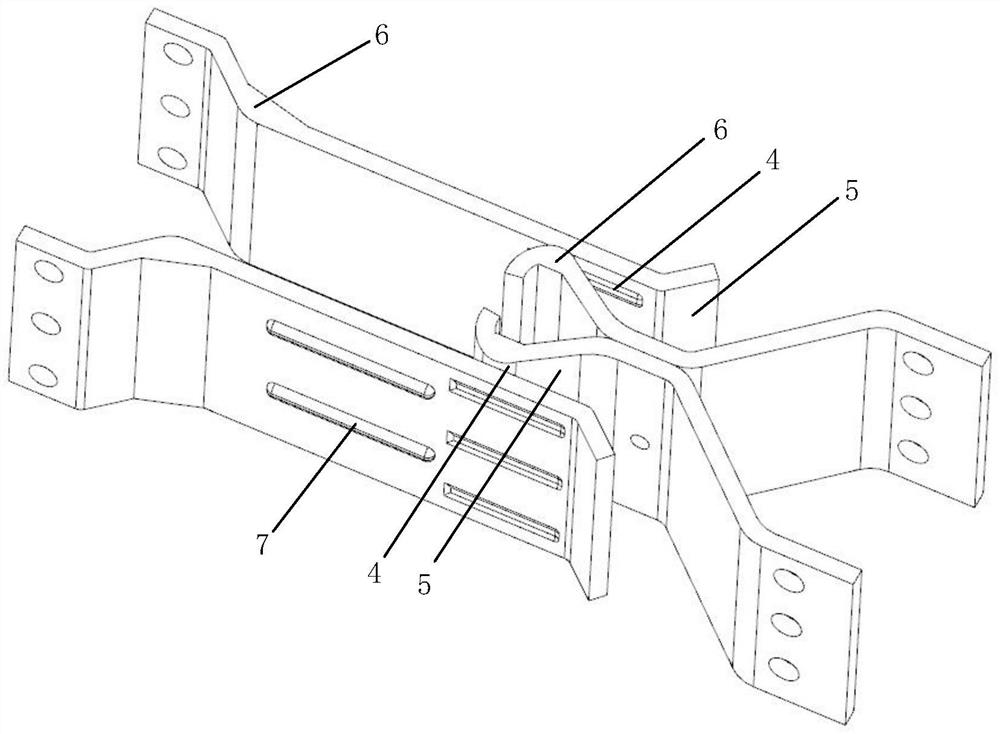
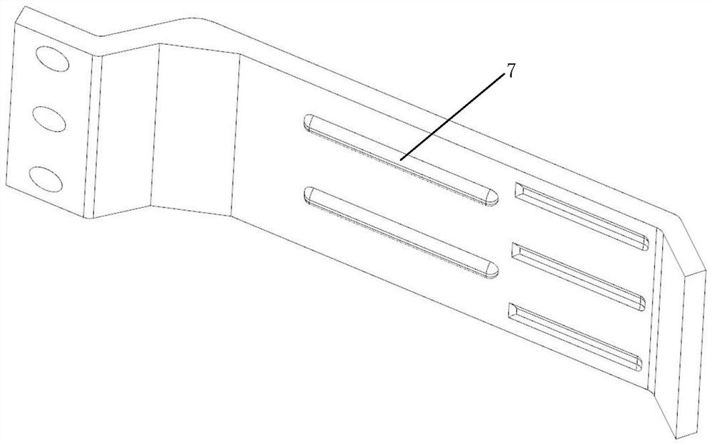
[0006] In order to solve the above problems, the present invention proposes a manufacturing method of a high-strength wear-resistant and corrosion-resistant contact, using copper-chromium (zirconium) alloy as the base material of the self-supporting contact, and covering the surface of the base material with thinner, corrosion-resistant Zinc electroplating layer, and a thick, high-conductivity, wear-resistant silver-antimony alloy layer is brush-plated on the contact area of ​​the contact, which improves the corrosion resistance and wear resistance of the contact, prolongs the service life of the contact, and solves the problem of spring Diversion problem, and improved the problem of environmental pollution in the preparation process

Method used


Image

  • Manufacturing method of high-strength wear-resistant corrosion-resistant contact
  • Manufacturing method of high-strength wear-resistant corrosion-resistant contact
  • Manufacturing method of high-strength wear-resistant corrosion-resistant contact

Examples


Embodiment 1

[0045] 1) The ingot of copper-chromium alloy with uniform composition is used as raw material, the mass percentage of chromium element in the raw material is 0.3%, and the rest is copper element; after the ingot is subjected to solution heat treatment, water quenching, scale removal and rolling, the obtained Alloy plate; the processing technology of solution heat treatment, water quenching, descaling and rolling is carried out according to the processing technology of copper-chromium alloy.

[0046] 2) Place the alloy plate obtained in step 1) in a steel mold or a graphite mold, and prepare a movable contact alloy base material and a static contact alloy base material by precision forging or stamping forming.

[0047] 3) The surface of the alloy base material of the moving contact and the alloy base material of the static contact are all electroplated with a zinc electroplating layer by electroplating. The thickness of the zinc electroplating layer of the moving contact is 20 μ...

Embodiment 2

[0051] 1) The ingot of copper-chromium-zirconium alloy with uniform composition is used as raw material, the mass percentage of chromium element in the raw material is 0.1%, the mass percentage of zirconium element is 0.05%, and the rest is copper element; the ingot is subjected to solution heat treatment, water quenching 1. After descaling and rolling, the alloy plate is obtained; the processing technology of the solution heat treatment, water quenching, descaling and rolling is carried out according to the copper-chromium alloy processing technology.

[0052] 2) Place the alloy sheet material obtained in step 1) in a steel mold or a graphite mold, and prepare a moving contact alloy base material and a static contact alloy base material by using a precision forging method. The bending area of ​​the base material adopts a forging method to make a thickened structure, and both the dynamic and static contact alloy base materials adopt a forging method to make reinforcing ribs.

...

Embodiment 3

[0057] 1) The ingot of copper-chromium-zirconium alloy with uniform composition is used as raw material, the mass percentage of chromium element in the raw material is 0.5%, the mass percentage of zirconium element is 0.03%, and the rest is copper element; the ingot is subjected to solution heat treatment, water quenching 1. After descaling and rolling, the alloy plate is obtained; the processing technology of the solution heat treatment, water quenching, descaling and rolling is carried out according to the copper-chromium alloy processing technology.

[0058] 2) Place the alloy sheet material obtained in step 1) in a steel mold or a graphite mold, and prepare a moving contact alloy base material and a static contact alloy base material by using a precision forging method. The bending area of ​​the base material adopts a forging method to make a thickened structure, and adopts a forging method to make a reinforcing rib on the static contact alloy base material.

[0059] 3) Th...


PUM

PropertyMeasurementUnit
thicknessaaaaaaaaaa
thicknessaaaaaaaaaa
thicknessaaaaaaaaaa

Abstract

The invention relates to a manufacturing method of a high-strength wear-resistant corrosion-resistant contact. The method comprises the following steps: performing solid solution heat treatment, water quenching, oxide skin removal and rolling on a copper-chromium (zirconium) alloy ingot to obtain an alloy plate; placing the obtained alloy plate in a die, and preparing alloy base materials of the movable contact and the static contact by forging or punch forming; electroplating zinc electroplating layers on the whole surfaces of the alloy base materials of the moving contact and the static contact; removing the zinc electroplating layer in the contact area of the moving contact and the static contact, and brushing a silver-antimony alloy layer to obtain a moving contact alloy structural member and a static contact alloy structural member; fixing the upper contact alloy structural member and the lower contact alloy structural member and forming the fixed connection with the disconnecting switch support. The copper-chromium (zirconium) alloy is adopted as a base material to manufacture the self-operated contact, the surface of the base material is covered with a thin and corrosion-resistant zinc electroplated layer, and a thick, high-conductivity and wear-resistant silver-antimony alloy layer is brushed and plated in a contact area of the contact, so that the corrosion-resistant effect and wear resistance of the contact are improved, a spring structure does not need to be arranged, and the problem of spring shunting is solved.

Description

technical field [0001] The invention belongs to the field of high-voltage electrical appliances, in particular to a method for manufacturing a high-strength wear-resistant and corrosion-resistant contact. Background technique [0002] Contacts of high-voltage isolating switches are one of the important conductor materials in substations. They are composed of moving contacts and static contacts. They are generally prepared by electroplating pure silver on the surface of pure copper. Pure copper has excellent electrical conductivity, thermal conductivity and ductility, and is the main material for making switch contacts. However, pure copper has low strength and poor corrosion resistance. The adverse effects on the conductivity of the contacts are: the conductivity of the copper oxide film is extremely poor , the contact resistance between the dynamic and static contacts after oxidation is very large; and the low strength of pure copper is easy to deform, which will cause the ...

Claims


Application Information

Patent Timeline
Patent Type & Authority Applications(China)
IPC IPC(8): H01H11/04C22C5/06C22C9/00C22F1/08C25D5/06C25D5/10C25D7/00
CPCH01H11/04C22F1/08C22F1/002C25D7/00C25D5/10C25D5/06C22C9/00C22C5/06
Inventor 邵星海曹阳杨倩倩刘源曹磊
Owner 清研特材科技(洛阳)有限公司
Learn More