
Transparent laminated glass based on grids, preparation method and window carrier

A laminated glass and transparent technology, applied in windshields, parallel glass structures, chemical instruments and methods, etc., can solve problems such as the inability to apply hyperboloid glass, affecting the sight of drivers and passengers, and the inability of flexible substrates to stretch, etc. Achieve the effect of large-area mass production, improved curved glass compatibility, improved safety and accuracy

Active Publication Date: 2022-05-13
SUZHOU INST OF NANO TECH & NANO BIONICS CHINESE ACEDEMY OF SCI
View PDF12 Cites 0 Cited by
  • Summary
  • Abstract
  • Description
  • Claims
  • Application Information

AI Technical Summary

Problems solved by technology

This method heats unevenly, slowly, and the opaque lines will block the driver's sight, so it is not suitable for use on the front windshield
Another method is to use a thin layer of metal, graphene or metal nanowires as an electric heating film to achieve a uniform heating effect (201810187994.0; 201220509608.3). Well, the higher the heating efficiency, but the conductivity and light transmittance of the graphene or metal nanowire film layer restrict each other. Under high light transmittance, the conductivity is poor, so that the heating power is low
The third method is to form a metal grid on the glass by sputtering metal and etching process, so as to achieve uniform heating and high heating efficiency performance (201710425909.5), but this method is costly and difficult to manufacture in large areas, and the line width is usually larger than 10 μm, visible to the naked eye, affects the sight of drivers and passengers; in addition, car window glass or aircraft windshield is curved, and high vacuum magnetron sputtering on curved glass will make the film layer uneven, so this method is different from that of curved glass. Process compatibility needs to be further improved
The current method used is to form a transparent electromagnetic shielding film on the optical window, such as sandwiching a conductive wire mesh between two layers of glass (200920157252.X, 201921189616.2). The conductive wire mesh has good shielding performance and high light transmittance, but The existing technical wire width is relatively wide, which affects the visual effect, and cannot be applied to hyperboloid glass
However, thin-line-width metal mesh transparent electromagnetic shielding films can be obtained on flexible substrates by photolithography and electroplating methods (such as patents 202011298220.9 and 201911068114.9), but flexible substrates are not stretchable, and when combined with glass with a large curvature , it is easy to form wrinkles, which makes the metal grid interface between the glass and the PET substrate more complicated, thus affecting the light transmittance

Method used


Image

  • Transparent laminated glass based on grids, preparation method and window carrier
  • Transparent laminated glass based on grids, preparation method and window carrier
  • Transparent laminated glass based on grids, preparation method and window carrier

Examples


Embodiment 11

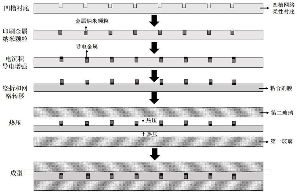
[0065] First, a groove structure is formed on the PET substrate (the groove structure is hexagonal, the period is 80 μm, the groove line width is 2.5 μm, and the groove depth is 3 μm), and then a 2 μm thick silver nanometer is formed in the groove by printing. Particle layer, at this time, the adhesion between the silver nanoparticles and the groove is 3B; then, 2 μm thick copper is deposited on the surface of the silver nanoparticles by electrodeposition, and its conductivity is further enhanced to form a metal mesh transparent conductive film; then use The roller with a roller diameter of 10mm is wound and folded 3 times, then the metal grid conductive film is placed on the PVB, and hot-pressed once with a 50°C roller to remove the PET, and the metal grid is transferred to the PVB at this time; finally The transferred PVB and the metal grid are sandwiched between two pieces of hyperbolic glass, and vacuum hot-pressed at 140°C for 1 hour to form a hyperbolic transparent electr...

Embodiment 12

[0067] First, a groove structure is formed on the PET substrate (the groove structure is a regular triangle, the period is 50 μm, the groove line width is 2 μm, and the groove depth is 0.2 μm), and then a 0.1 μm thick silver nanometer is formed in the groove by printing. Particle layer, at this time, the adhesion between the silver nanoparticles and the groove is 3B; then deposit 0.1 μm thick copper on the surface of the silver nanoparticles by electrodeposition, further enhance its conductivity, and form a metal grid transparent conductive film; then Use a roller with a diameter of 1mm to fold 3 times, then place the metal grid conductive film on the PVB, and use a 40°C roller to heat press 3 times to remove the PET. At this time, the metal grid is transferred to the PVB; finally The transferred PVB and metal grid are sandwiched between two pieces of hyperbolic glass, and vacuum hot-pressed at 100°C for 1 hour to form a hyperbolic transparent electromagnetic shielding glass. ...

Embodiment 13

[0069] First, a groove structure (groove structure is square, period 200 μm, groove line width 7 μm, groove depth 14 μm) is formed on the PET substrate, and then a 2 μm thick silver nanoparticle layer is formed in the groove by printing method, At this time, the adhesion between the silver nanoparticles and the groove is 2B; then, 12 μm thick copper is deposited on the surface of the silver nanoparticles by electrodeposition, and its conductivity is further enhanced to form a metal mesh transparent conductive film; then use the roller diameter Fold once for a 10cm roller, place the metal grid conductive film on the PVB, and heat press it twice with a 100°C roller to remove the PET. At this time, the metal grid is transferred to the PVB; finally, the transferred PVB It is sandwiched between two pieces of hyperbolic glass with a metal grid, and vacuum-pressed at 150°C for 1 hour to form a hyperbolic transparent electromagnetic shielding glass. The square resistance of the metal ...


PUM

PropertyMeasurementUnit
widthaaaaaaaaaa
transmittivityaaaaaaaaaa

Abstract

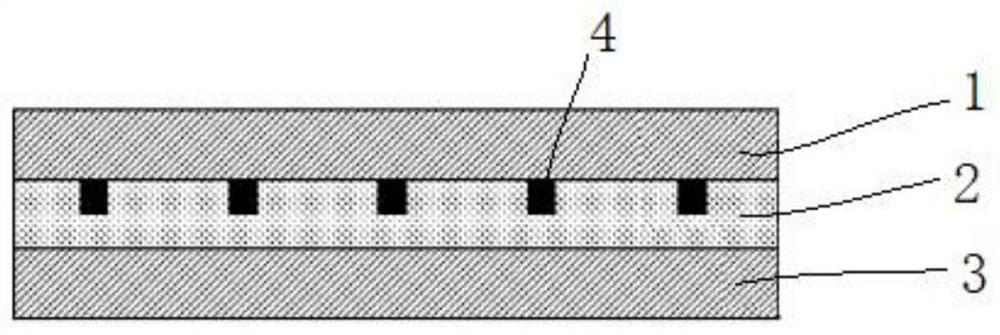
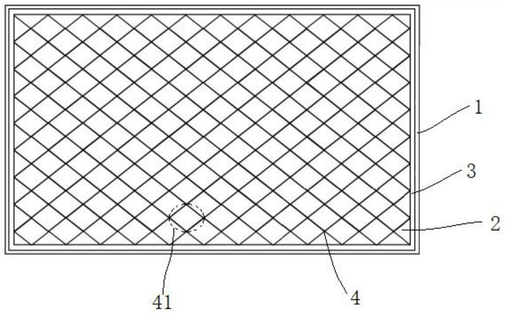
The invention discloses transparent laminated glass based on grids, a preparation method and a window carrier, the laminated glass comprises first glass, an interlayer and second glass which are arranged in sequence, the interlayer comprises a filling layer and a conductive grid, at least part of the conductive grid is provided with repetitive grid units, the repetition period of the grid units is 30-200 microns, and the first glass and the second glass are sequentially arranged. The width of the wires forming the conductive grid is 2-10 [mu] m. By optimizing the structure and preparation of the conductor grid of the laminated glass, the aspects of high light transmittance, high conductivity, narrow line width, curved glass compatibility and the like are remarkably improved, and the integrated preparation of the planar / curved laminated glass is realized, so that the safety and precision of a glass product are improved.

Description

technical field [0001] The invention relates to glass technology, in particular to a grid-based transparent laminated glass, a preparation method and a window carrier. Background technique [0002] With the advent of the 5G era, smart electronic products have been rapidly developed and widely used, making products in some scenarios (such as automotive glass and aircraft optical windows) put forward higher requirements. In terms of automotive glass, under high temperature, high humidity and foggy conditions, the fog on the glass will affect the observation of road traffic conditions by the probe or drivers and passengers, thus making drivers and passengers face traffic safety hazards. At present, the most commonly used method to solve the fog on the automobile glass is to form a wire on the glass, and achieve the effect of defrosting and defogging through electric heating (02810897.3). This method heats unevenly, slowly, and the opaque lines will block the driver's sight, so...

Claims


Application Information

Patent Timeline
Patent Type & Authority Applications(China)
IPC IPC(8): B32B17/10B32B27/30B32B3/30B32B3/08B32B7/12B32B37/06B32B37/10B32B37/12B32B38/00C03C27/12E06B3/66B60J1/00B63B19/00B63B19/02B64C1/14
CPCB32B17/10B32B17/10036B32B17/10385B32B17/10871B32B17/10899B32B27/306B32B3/30B32B3/08B32B7/12E06B3/66B60J1/001B64C1/1492B63B19/00B63B19/02B32B2419/00B32B2605/00B32B2605/12B32B2605/18B32B2307/412B32B2307/202B32B2307/212B32B2329/06B32B2355/00
Inventor 陈小连苏文明徐文亚聂书红张硕裴芳芳
Owner SUZHOU INST OF NANO TECH & NANO BIONICS CHINESE ACEDEMY OF SCI
Learn More