Eureka AIR delivers breakthrough ideas for toughest innovation challenges, trusted by R&D personnel around the world.

Gate dielectric thin film transistor for SiC-based field effect transistor and preparation method of gate dielectric thin film transistor

A field effect transistor, thin film transistor technology, applied in transistors, semiconductor/solid-state device manufacturing, semiconductor devices and other directions, can solve the high technical threshold of semi-insulating silicon carbide layer, transistor silicon dioxide dielectric is broken down, and it is difficult to use silicon carbide. Advantages and other issues, to achieve the effect of improving breakdown resistance and reliability, no surface dangling bonds, and improving carrier mobility

Active Publication Date: 2022-05-24
浙江芯科半导体有限公司
View PDF4 Cites 0 Cited by
  • Summary
  • Abstract
  • Description
  • Claims
  • Application Information

AI Technical Summary

Problems solved by technology

However, silicon carbide-based MOSFETs, IGBTs, and SBD devices at home and abroad have encountered great challenges in terms of gate dielectric layer reliability and electron mobility, because the dielectric constant of SiC (9.7) is almost the same The dielectric constant (3.9) of the silicon dioxide layer formed at the bottom is three times that of silicon dioxide, and the internal electric field concentration effect of silicon dioxide is very obvious. Therefore, the operation of the transistor is very susceptible to the danger of the breakdown of the silicon dioxide dielectric, and it is difficult to play the role of silicon carbide. superiority
Importantly, the accumulation of element C in the process of thermally oxidizing SiC substrates to form SiO2 leads to a high defect density at the SiO2 / SiC interface, which enhances the scattering effect and greatly reduces the The mobility of
In addition, the technical threshold of silicon carbide homoepitaxial semi-insulating silicon carbide layer is high, the growth process is complex, the growth rate is slow, and the repeatability is low, making its cost high

Method used


Image

  • Gate dielectric thin film transistor for SiC-based field effect transistor and preparation method of gate dielectric thin film transistor
  • Gate dielectric thin film transistor for SiC-based field effect transistor and preparation method of gate dielectric thin film transistor
  • Gate dielectric thin film transistor for SiC-based field effect transistor and preparation method of gate dielectric thin film transistor

Examples


Embodiment 1

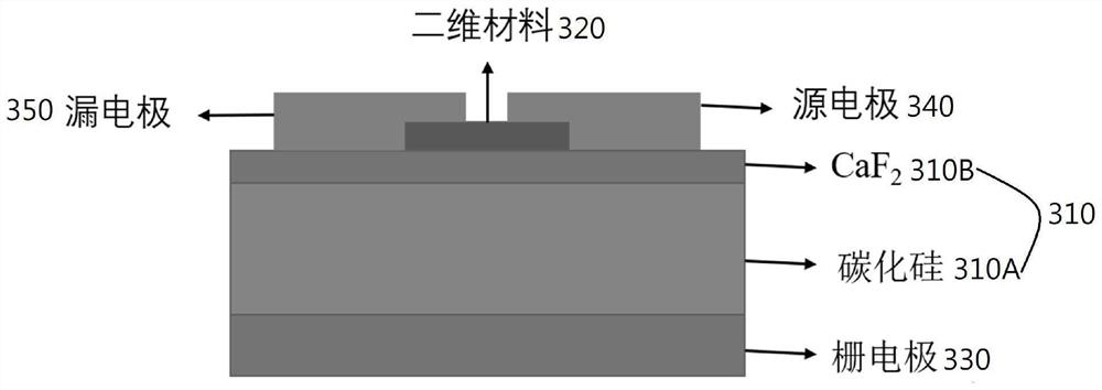
[0040] refer to image 3 , a gate dielectric thin film transistor 30 for a SiC-based field effect transistor, comprising a silicon carbide substrate 310A and a calcium fluoride film 310B, the calcium fluoride film 310B is deposited on the silicon carbide substrate 310A to form CaF 2 / SiC substrate 310, a two-dimensional material 320 is disposed on the calcium fluoride film 310B, and a two-dimensional material 320 is disposed on the calcium fluoride film 310B in a transfer manner.

[0041] As a further illustration of this example, the CaF 2 / SiC substrate 310 is vapor-deposited a metal film on the side of silicon carbide 310A opposite to calcium fluoride film 310B as gate electrode 330 , and annealed at 1000° C. for 5 minutes under nitrogen.

[0042] As a further description of this embodiment, the source electrode 340 and the drain electrode 350 are obtained by vapor-depositing metal on the two-dimensional material 320 , respectively. Using the laser direct writing method, ...


PUM

PropertyMeasurementUnit
Thicknessaaaaaaaaaa
Bandgapaaaaaaaaaa

Abstract

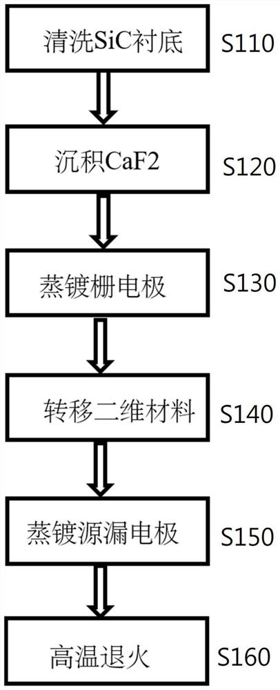
The invention relates to a gate dielectric thin film transistor for a SiC-based field effect transistor and a preparation method of the gate dielectric thin film transistor. The preparation method comprises the following steps: providing a cleaned SiC substrate; a CaF2 thin film is deposited on the cleaned SiC substrate, and a CaF2 / SiC substrate is formed; evaporating a metal film on one side of the silicon carbide on the CaF2 / SiC substrate to serve as a gate electrode; the two-dimensional material is transferred to the CaF2 / SiC substrate; evaporating metal on the two-dimensional material to respectively obtain a source electrode and a drain electrode; and annealing by using inert gas to complete the preparation of the transistor. The transistor structurally comprises a gate electrode / SiC / CaF2 / two-dimensional material / source and drain electrodes from bottom to top. The gate dielectric film CaF2 prepared by the invention has the advantages of high air stability, no surface dangling bond, high dielectric constant, large forbidden bandwidth, low interface state density and the like.

Description

technical field [0001] The invention belongs to the field of gate dielectric layer growth and device application, and in particular relates to a gate dielectric thin film transistor used in a SiC-based field effect transistor and a preparation method thereof. Background technique [0002] As a popular semiconductor material for power devices, silicon carbide is one of the third-generation wide-bandgap semiconductors with a band gap between 2.3-3.3eV. It not only has a large electron saturation drift speed, high breakdown field strength, and radiation resistance It has the advantages of high chemical stability, high thermal conductivity, excellent physical and chemical stability, strong radiation resistance and mechanical strength. Based on these advantages, silicon carbide can be used to fabricate high-frequency, high-power devices for use in extreme environments. However, domestic and foreign silicon carbide-based MOSFETs, IGBTs, and SBD devices have encountered great chal...

Claims


Application Information

Patent Timeline
IPC IPC(8): H01L29/786H01L29/16H01L21/34
CPCH01L29/66969H01L29/78696H01L29/1608
Inventor 李京波岳倩高伟王小周张峰
Owner 浙江芯科半导体有限公司
Why Eureka
Eureka Blog
Learn More