Preparation method of bone defect repair stent

A bone defect and bone repair technology, applied in the direction of bone implants, can solve the problems of lack of biological activity and poor mechanical properties, and achieve the effect of promoting regeneration

Pending Publication Date: 2022-07-22
XIEHE HOSPITAL ATTACHED TO TONGJI MEDICAL COLLEGE HUAZHONG SCI & TECH UNIV
View PDF0 Cites 1 Cited by
  • Summary
  • Abstract
  • Description
  • Claims
  • Application Information

AI Technical Summary

Problems solved by technology

Most of the bone repair materials currently used have the following two s

Method used


Image

  • Preparation method of bone defect repair stent
  • Preparation method of bone defect repair stent
  • Preparation method of bone defect repair stent

Examples


Embodiment 1

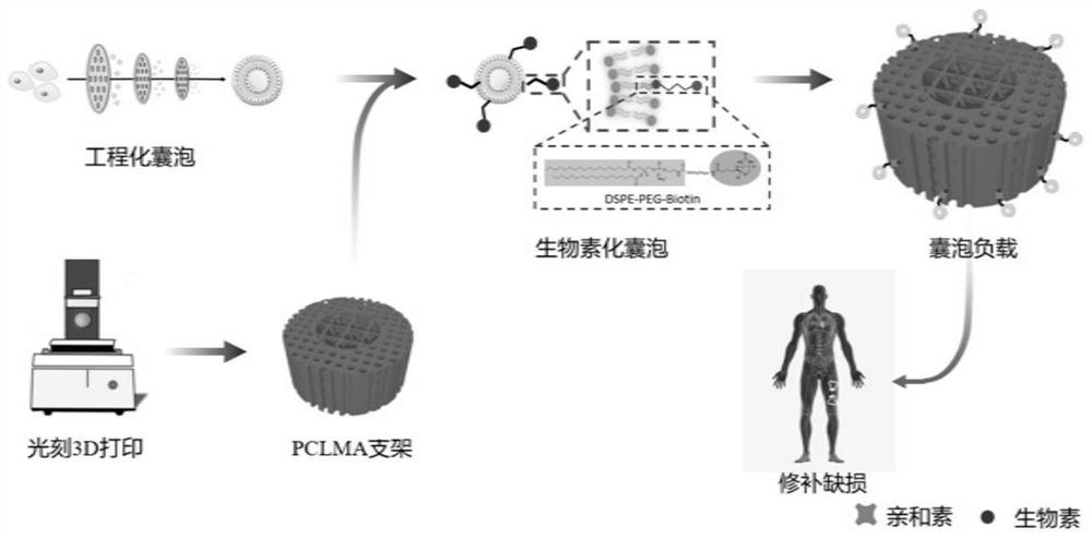
[0040] A method for manufacturing a scaffold for repairing bone defects, comprising the following steps:

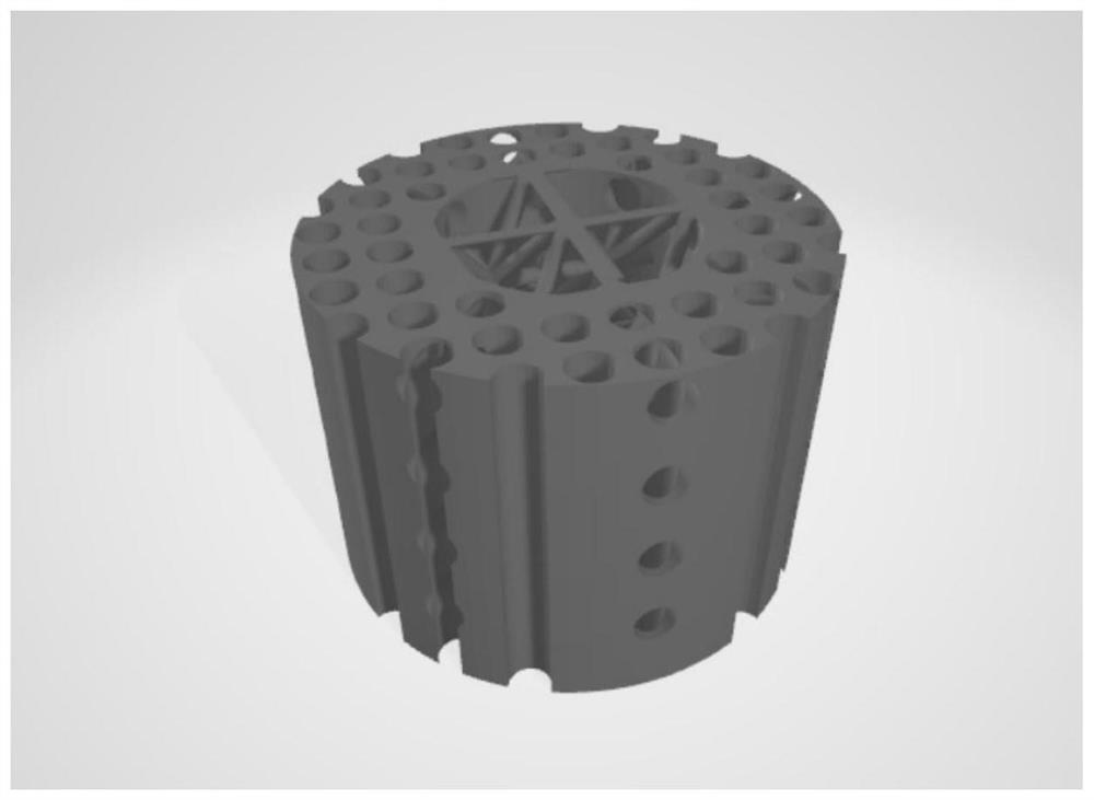
[0041] (1) The patient took the CT of the bone defect before the operation, saved it in DICOM format and imported it into the surgical planning software (ProPlan 2.1, Materialise NV, Belgium), and reconstructed the three-dimensional model of the defect. The software can then automatically generate the required bone tissue length, diameter, and surgical plan. Export the scheme to CAD software in STL format;

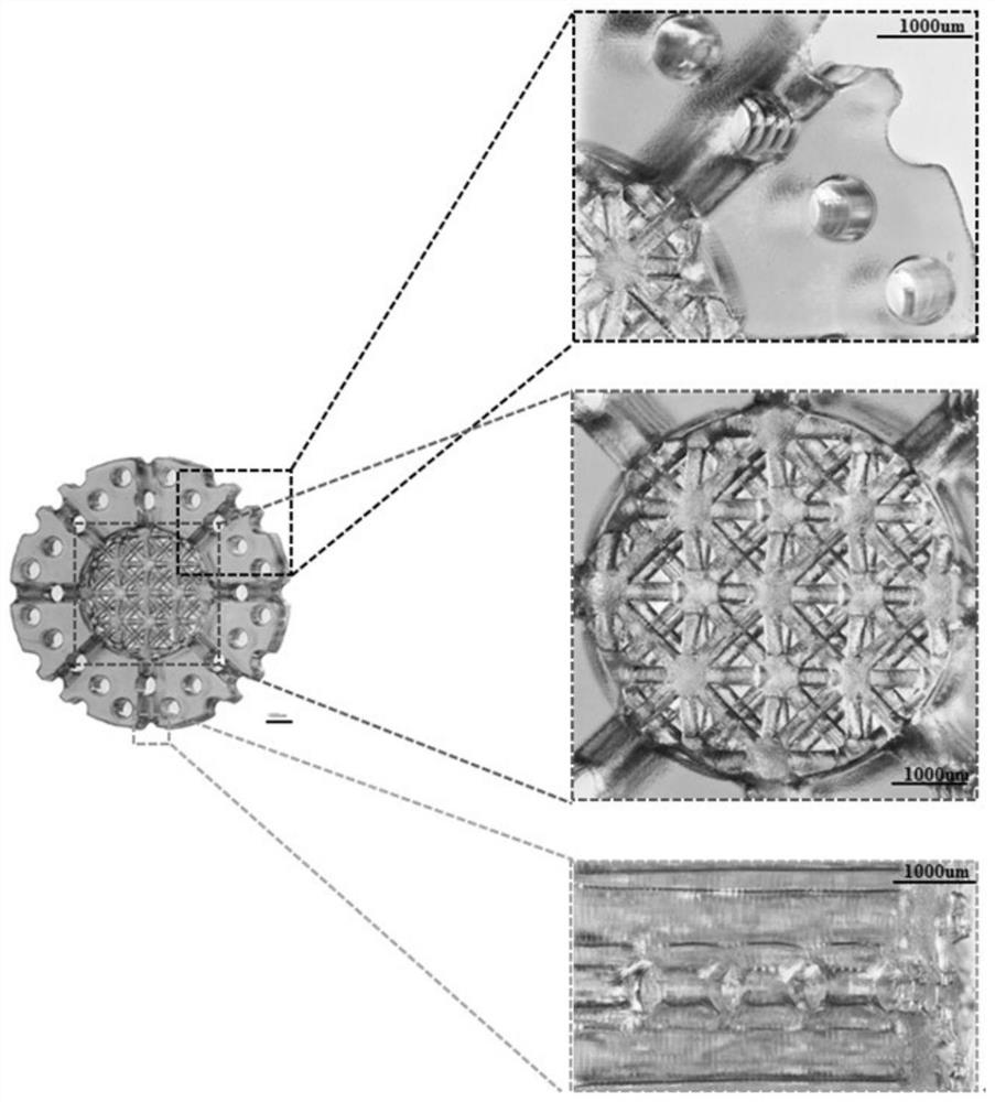
[0042] (3) The photoinitiator TPO-L was dissolved in photocurable polycaprolactone (PCLMA) at a concentration of 1.8% w / v and the light absorber β-carotene at a concentration of 0.09% w / v, to obtain a bone scaffold that can be used for printing. liquid ink;

[0043] (4) Aseptically treating the bone scaffold printing liquid ink obtained in step (3), adding a centrifuge tube, repeatedly blowing and beating with a pipette, and placing it in a centrifuge at 3700 r / min fo...

Embodiment 2

[0054] A method for manufacturing a scaffold for repairing bone defects, comprising the following steps:

[0055] (1) Obtain the imaging data of the patient's bone defect through clinical imaging CT and MRI scanning, and then use CAD software to perform 3D modeling to obtain slice STL format files;

[0056] (2) Based on the above data analysis and model making, a personalized bone repair scaffold with a specific shape suitable for the patient's bone defect is designed;

[0057] (3) The photoinitiator TPO-L was dissolved in photo-curable polycaprolactone (PCLMA) at a concentration of 1.5% w / v and the light absorber β-carotene at a concentration of 0.06% w / v to obtain a bone scaffold that can be used for printing. liquid ink;

[0058] (4) Aseptic treatment of the bone scaffold printing liquid ink obtained in step (3), adding a centrifuge tube, repeatedly blowing and beating with a pipette gun, and placing it in a centrifuge at 3500 r / min for 3 minutes to remove air bubbles, and...


PUM

PropertyMeasurementUnit
Particle sizeaaaaaaaaaa

Abstract

The invention provides a preparation method of a bone defect repair stent, which comprises the following steps of: obtaining imaging data of a bone defect part through modes of clinical imaging CT (Computed Tomography), MRI (Magnetic Resonance Imaging) scanning and the like, then modeling by utilizing CAD (Computer Aided Design) software according to the specific form of the bone defect of a patient, outputting an STL (Standard Template Library) format file of the bone tissue repair stent, and carrying out A biodegradable material photocuring polycaprolactone is used as a printing raw material, a photoetching 3D printer is used for stacking and forming the material, and the porous bone repair scaffold suitable for the form of a defected part of a patient is printed. And grafting the biotinylated vesicles to the surface of the scaffold by using a biotin-avidin system to construct the bioactive scaffold with the surface loaded with the stem cell vesicles. According to the invention, the stem cell vesicles are loaded on the photocuring printed porous bone scaffold by using a biotin-avidin system, so that the personalized customization of the bone scaffold can be realized, and the scaffold has the effect of accelerating bone defect repair by using active substances in the stem cell vesicles.

Description

technical field [0001] The invention relates to the field of tissue engineering bone defect repair, in particular to a preparation method of a bone defect repair bracket. Background technique [0002] Bone shortage caused by trauma or surgery is called bone defect, such as comminuted fractures, open fractures, large bone tissue defects caused by trauma, inflammation, bone disease and other factors in the pathological process, and osteonecrosis caused by inflammation. , Bone infarction or large bone necrosis caused by avascular necrosis. Due to the existence of bone defects, bone nonunion, delayed union or nonunion, and local dysfunction are often caused. Therefore, the repair and functional reconstruction of segmental bone defects caused by trauma and disease has always been an urgent problem to be solved in clinical orthopaedics. The repair of segmental bone defects includes autologous bone, allogeneic bone, tissue engineering bone transplantation and artificial bone repla...

Claims


Application Information

Patent Timeline
IPC IPC(8): A61F2/28
CPCA61F2/28A61F2/30942A61F2002/30952A61F2002/30985
Inventor 姜文彬孙家明陈雳风汪振星刘剑张郭陈宇轩詹怡辰张一帆
Owner XIEHE HOSPITAL ATTACHED TO TONGJI MEDICAL COLLEGE HUAZHONG SCI & TECH UNIV
Why Eureka
Try Eureka