
Fuel cell gas diffusion layer continuous preparation method and production line

A technology of gas diffusion layer and conductive carbon layer, which is applied in the direction of fuel cells, electrical components, battery electrodes, etc., can solve the problems of prolonging the preparation time of gas diffusion layer, poor uniformity, and failure to achieve uniformity of diffusion layer coating, and achieve The effect of avoiding the problem of slurry penetration and improving the production efficiency

Pending Publication Date: 2022-07-29
姜永燚
View PDF0 Cites 0 Cited by
  • Summary
  • Abstract
  • Description
  • Claims
  • Application Information

AI Technical Summary

Problems solved by technology

However, the diffusion layer plays the role of supporting the catalytic layer, stabilizing the electrode structure, and conducting electrons between the bipolar plate and the catalytic layer, realizing "water-gas" two-phase flow and current collection, hydrophobicity to the carbon substrate, and micropores The uniformity of the layer is relatively high. For the traditional method of soaking the hydrophobic agent on the carbon substrate, since the direct soaking method is to make the carbon substrate quickly contact with a large amount of hydrophobic agent in a short period of time, this process cannot guarantee the carbon paper. The water content at each area, so the uniformity of the hydrophobic agent in the carbon paper cannot be controlled; for the traditional method of doping the hydrophobic agent in the microporous layer slurry and then coating the mixed slurry, due to the ethanol in the slurry It is easy to agglomerate with the hydrophobic agent, resulting in poor uniformity of the mixed slurry before coating, so that the uniformity of the diffusion layer coating is far from being met after coating
[0004] In addition, in the traditional gas diffusion layer preparation process, after the carbon paper is impregnated with a hydrophobic agent, it needs to be roasted. After the carbon paper that has completed the hydrophobic treatment is coated with a conductive paste to form a microporous layer, it is also necessary to carry out the overall process. Roasting treatment, the two-step roasting process greatly prolongs the preparation time of the gas diffusion layer, resulting in low efficiency of the gas diffusion layer preparation

Method used


Image

  • Fuel cell gas diffusion layer continuous preparation method and production line
  • Fuel cell gas diffusion layer continuous preparation method and production line
  • Fuel cell gas diffusion layer continuous preparation method and production line

Examples


Embodiment 1

[0061] Step (1): prepare a pore-forming agent solution: weigh 100 g of ammonium bicarbonate and 2000 ml of deionized water, mix them evenly, and set aside for later use;

[0062] Configure conductive carbon slurry: weigh 200g of graphene, 800ml of deionized water, and 3600ml of anhydrous ethanol respectively, mix them evenly, and use a high-speed mixer to stir for 30min at a speed of 1100r / min.

[0063] To configure the hydrophobic agent solution: Weigh 100 g of PTFE emulsion and 2000 ml of deionized water, mix them evenly, and place them in an ultrasonic cleaning machine for ultrasonic treatment for 10 min, for later use.

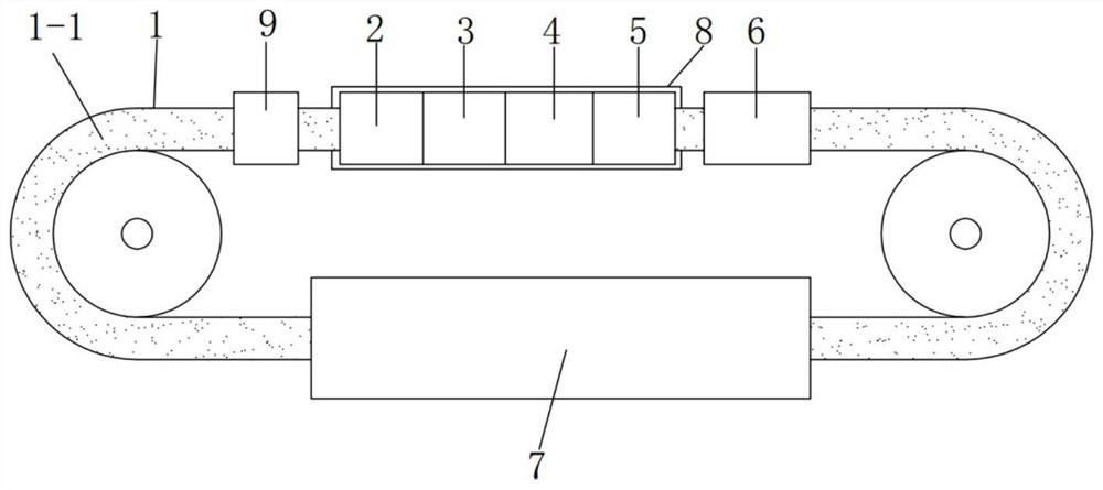
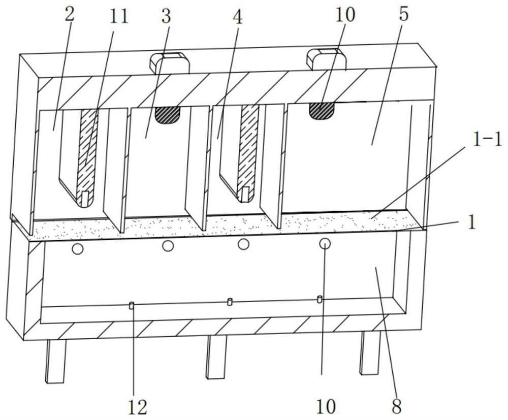
[0064] The prepared pore-forming agent solution and conductive carbon slurry are respectively fed into the first slurry spraying area 2 and the second slurry spraying area 4, and communicated with the nozzles in each area respectively for use; the configured hydrophobic agent The solution is fed into the first atomization zone 3, the second atomization zon...

Embodiment 2

[0075] Preparation of pore-forming agent solution: Weigh 100g of sodium carbonate and 2500ml of deionized water and mix them evenly for later use;

[0076] Configure the conductive carbon slurry: respectively weigh 200g of acetylene black, 1600ml of deionized water, and 4200ml of ethanol, mix them evenly, and stir with a high-speed mixer for 30min at a speed of 1100r / min, and take them out for use after the time is up;

[0077] To configure the hydrophobic agent solution: Weigh 100 g of polyvinylidene fluoride emulsion and 2500 ml of deionized water, mix them evenly, and place them in an ultrasonic cleaning machine for ultrasonic treatment for 10 min, for use.

[0078]The prepared pore-forming agent solution and conductive carbon slurry are respectively fed into the first slurry spraying area 2 and the second slurry spraying area 4, and communicated with the nozzles in each area respectively for use; the configured hydrophobic agent The solution is fed into the first atomizati...

Embodiment 3

[0089] Preparation of pore-forming agent solution: Weigh 100g of sodium bicarbonate and 3000ml of deionized water and mix them evenly for later use;

[0090] Configure the conductive carbon paste: weigh 200g of carbon nanotubes, 2400ml of deionized water, and 4800ml of ethanol, respectively, and mix them, and use a high-speed mixer to stir for 30 minutes at a speed of 1100 r / min.

[0091] To configure the hydrophobic agent solution: Weigh 100 g of ethylene-tetrafluoroethylene emulsion and 3000 ml of deionized water, mix them evenly, and place them in an ultrasonic cleaning machine for sonication for 10 min for later use.

[0092] The prepared pore-forming agent solution and conductive carbon slurry are respectively fed into the first slurry spraying area 2 and the second slurry spraying area 4, and communicated with the nozzles in each area respectively for use; the configured hydrophobic agent The solution is fed into the first atomization zone 3, the second atomization zone ...


PUM


Abstract

The invention discloses a preparation method and a production line of a gas diffusion layer for a fuel cell, and the preparation method comprises the following steps: spraying a pore-forming agent on the surface of a carbon base material, directly coating slurry on the basis that carbon paper is not hydrophobic, then realizing hydrophobic treatment of the carbon base material and a microporous layer by utilizing an atomization mode, and finally roasting, thereby obtaining the gas diffusion layer for the fuel cell. The uniformity of hydrophobic performance of the carbon substrate and the microporous layer is effectively improved, so that the overall uniformity of the gas diffusion layer of the fuel cell is improved, and the performance of the fuel cell is improved; in the production line, carbon paper can be cyclically conveyed in a rotary mode through the annular conveying track, then slurry can be conveniently sprayed and fed in batches and in a component mode, the feeding amount can be more accurately controlled, equipment can be cyclically used on the basis that the cost of other equipment is not increased, and the production line is suitable for batch production.

Description

technical field [0001] The invention relates to the field of fuel cells, in particular to a continuous preparation method and production line for a gas diffusion layer of a fuel cell. Background technique [0002] In the proton exchange membrane fuel cell, the gas diffusion layer plays a lot of roles. When the battery is working, the reactive gas with a certain humidity must first pass through the gas diffusion layer to the active site of the catalytic layer before participating in the electrochemical reaction. At the same time, the catalytic The water generated by the layer must be discharged in time through the gas diffusion layer to facilitate the smooth progress of the electrochemical reaction. In addition to the functions of conducting gas and expelling water, the microporous layer of the gas diffusion layer has a certain "water management" function, which can also reduce the contact resistance between the catalytic layer and the support layer. As one of the important ...

Claims


Application Information

Patent Timeline
Patent Type & Authority Applications(China)
IPC IPC(8): H01M8/0234H01M8/0245H01M4/88
CPCH01M8/0234H01M8/0245H01M4/8807Y02E60/50
Inventor 姜永燚
Owner 姜永燚
Learn More