

Transparent laminate having low emissivity
A low-radiation, multi-layer body technology, applied in coating, layered products, sputtering coating, etc., can solve problems such as unstable pressure, uneven film quality, unstable spraying rate, etc., to improve durability and wear resistance, crystallization inhibition effect
- Summary
- Abstract
- Description
- Claims
- Application Information
AI Technical Summary
Problems solved by technology
Method used
Image

Examples
Embodiment 1
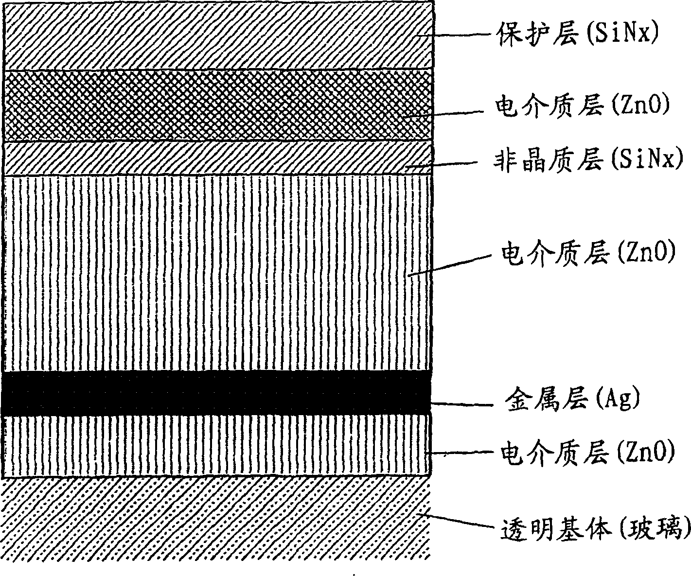
[0050] use Figure 11 The shown load-locked linear magnetron spraying device with 5 sets of cathodes will figure 1 The structure shown, that is, glass / ZnO / Ag / ZnO / SiN x / ZnO / SiN x A low-emissivity transparent multilayer body composed of a dielectric / silver / dielectric interlayer structure is formed into a film on one side surface of a common float glass with a thickness of 3mm×2500mm×1800mm.
[0051] From Figure 11 The inlet of the spraying device shown conveys the cleaned plate glass (G) to the load lock chamber (1), vacuum exhausts to a predetermined pressure, and conveys it to the coating chamber (2), after which the spraying gas is introduced into In the coating chamber (2), it is adjusted to a predetermined pressure balanced with the exhaust pump, and then the cathode (3) is energized to generate discharge, and the material set on each cathode is sprayed to form a film.
[0052] In addition, in this example, the glass was not particularly heated at the time of plating...
Embodiment 2
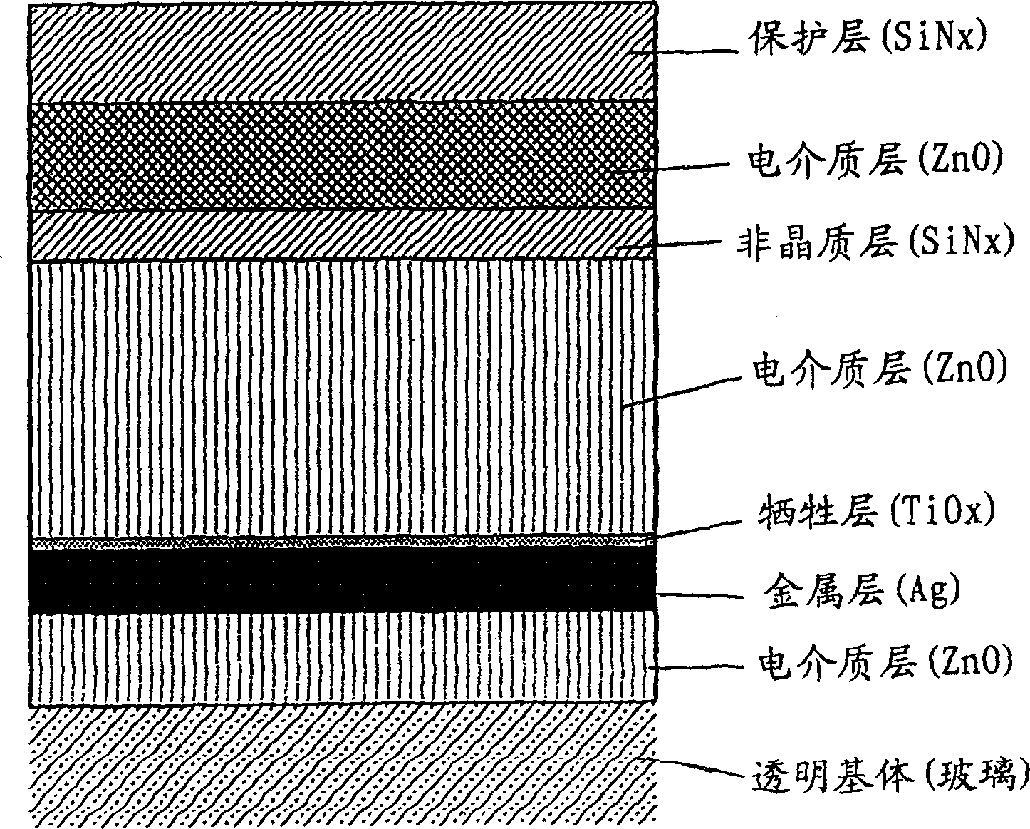
[0060] Utilize and embodiment 1 same sputtering apparatus, will and image 3 The same structure, that is, glass / ZnO / Ag / TiO x / ZnO / SiN x / ZnO / Ag / TiO x / ZnO / SiN x The low-emissivity transparent multilayer body composed of dielectric / silver / dielectric / silver / dielectric interlayer structure is formed into a film on one side surface of the same float glass in the following manner.
[0061] First, introduce oxygen into the chamber to make the pressure 0.40Pa, pass a direct current of 55kW to the cathode (3b) with a zinc target (size: 3100mm×330mm) to produce reactive spraying, and move the glass back and forth under the cathode , forming a zinc oxide film as the first layer.
[0062] Then, the gas in the chamber is switched to argon, and its pressure is 0.45Pa, and a direct current of 8kW is passed to the cathode (3c) provided with a silver target (size: 3100mm×330mm), while a titanium target (size: 3100mm) is provided. × 330 mm) of the cathode (3d) 8kW direct current, by passi...
Embodiment 3
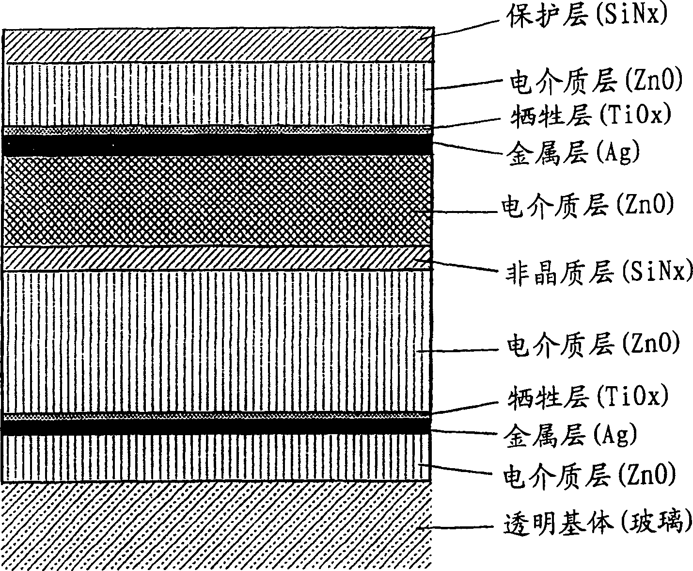
[0067] Utilize and embodiment 1 identical sputtering device, will and Figure 5The same structure, that is, glass / ZnO / Ag / TiO x / ZnO / SiN x / ZnO / SiN x / ZnO / Ag / TiO x / ZnO / SiN x A low-emissivity transparent multilayer body having a sandwich structure of dielectric / silver / dielectric / silver / dielectric was formed on one surface of the same float glass as follows.
[0068] Using the same method as in Example 2, the zinc oxide film of the first layer, the silver film of the second layer, the titanium film of the third layer (after functioning as a sacrificial layer, it becomes a titanium oxide film), the fourth layer of Zinc oxide film, aluminum-added silicon nitride film in the fifth layer, and zinc oxide film in the sixth layer.
[0069] Next, the aluminum-added silicon nitride film of the seventh layer and the zinc oxide film of the eighth layer are formed by the same method as the fifth layer and the sixth layer, and then, the second layer, the third layer, and the fourth laye...
PUM
| Property | Measurement | Unit |
|---|---|---|
| Radius | aaaaa | aaaaa |
Abstract
Description
Claims
Application Information