Method and system for high speed laser directly writing of diffraction light change image

A laser direct writing and diffracting light technology, which is applied in the direction of diffraction grating, optics, optical elements, etc., can solve the problems of short beam coherence length, inability to generate interference light field, and inability to write directly in micron-scale fringe lithography

Active Publication Date: 2006-06-14
SUZHOU UNIV +1
View PDF2 Cites 28 Cited by
  • Summary
  • Abstract
  • Description
  • Claims
  • Application Information

AI Technical Summary

Problems solved by technology

However, due to different uses, laser marking and drilling tools need to obtain a sufficiently high power density. Therefore, the beam output by this type of Nd:YAG laser is a multi-transverse mode spot, the beam coherence length is extremely short, and the spot quality is poor ( m 2 <10), can not produce sufficient quality interference light field
At the same time, the thermal effect of Nd:YAG laser 1060nm and 532nm light is very obvious when processing the metal surface. It mainly relies on focusing to form high energy density, and locally generates high temperature to ablate the material. It basically belongs to the category of thermal processing, and the processing accuracy is limited. On the other hand, the photoresist is not sensitive to 1060nm and 532nm light, therefore, the Nd:YAG laser used for laser marking cannot form high-quality micron-scale interference fringes, and it cannot be used for photolithographic direct writing of micron-scale fringes

Method used


Image

  • Method and system for high speed laser directly writing of diffraction light change image
  • Method and system for high speed laser directly writing of diffraction light change image
  • Method and system for high speed laser directly writing of diffraction light change image

Examples


Embodiment 1

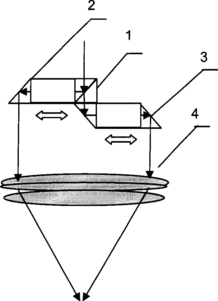
[0046] Embodiment one: see attached Figure 2-4 As shown, a method for making diffractive light-variable images converts the image distribution into a pulse control signal, adjusts the steering of the beam splitting elements (6, 7) according to the orientation of the unit grating and the space-frequency synchronization, and simultaneously performs interference between the optical head and Platform movement, high-speed rotation of beam-splitting elements and light pulse input, line by line detour, continuous pulse exposure on recording materials, platform, interference optical head, and beam-splitting elements do not need to pause during exposure until the entire image is produced. For how the system works, see Figure 4 .

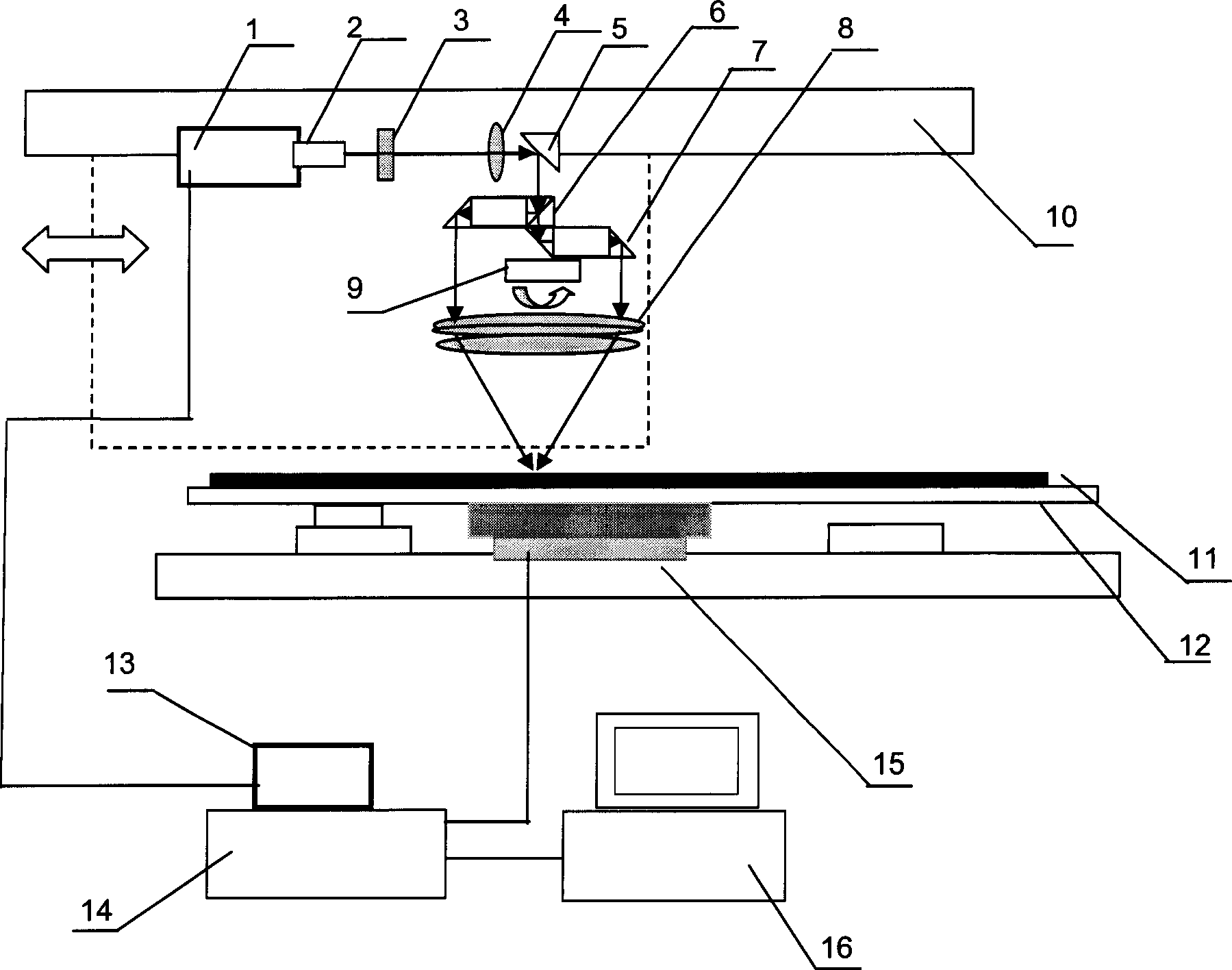
[0047] The laser lithography direct writing system that realizes the above method includes a DPSSL laser light source 1 output by ultraviolet light with a TTL signal interface, a beam expander and a collimating mirror 2, an iris diaphragm 3, a lens 4, a mi...

Embodiment 2

[0049] Embodiment two: see attached Figure 5 And attached Image 6 As shown, a lithographic direct writing system for making digital diffraction optically variable images, including a laser light source 1, a beam expander and a collimating mirror 2, a variable rectangular diaphragm 3, and an imaging system before beam splitting (lens f1 , f2 and the diaphragm form a 4F system with a miniature function), an optical path system composed of an imaging system after beam splitting (including a beam splitting element 18, an imaging lens group 8, and a high-speed turntable 9), the above-mentioned light source, an imaging system before beam splitting, The interferometric optical head composed of the post-beam imaging system is assembled on the X-direction horizontal movement system 10, the recording material 11 is placed on the Y-direction movement table 12, and the power supply 13 including TTL and power control, and the motion control system 14 , 15 and computer 16.

[0050] The ...

example 3

[0052] Example 3: A method for making a diffractive optically variable image. First, the image is decomposed into different sub-images according to the orientation of the interference fringes, and each sub-image is continuously exposed. During the exposure of the sub-images, the grating in the optical head does not need Rotation, the beam splitting grating needs to be rotated only when switching between sub-images. This production method avoids large-angle rotation during continuous operation, and improves the continuity of lithography operation and the production quality of diffractive light-variable images.

[0053] The overall structure of the laser direct writing system in this embodiment is the same as that in Embodiment 1.


PUM

PropertyMeasurementUnit
wavelengthaaaaaaaaaa
lengthaaaaaaaaaa

Abstract

The invention relates to diffracted light image changing high speed laser write through method. It includes the following steps: do electrostatic image for incidence parallel light reaches beam-splitting element though diaphragm; gathering the beam-slitting light to produce interference fringe optical field; orderly photoengraving interference fringe with different trend to form micro light grating image. Its features are that it is adopted solid state ultraviolet laser to produce laser beam; and it is used TTL signal control to realize laser beam pulse output; the two sets of the laser beam have zero optical path difference; optical system and photoresist dry plate are moved on two one dimension directions which are vertical with each other; photolithography is adopted continual motion, continual pulse exposing type. Thus the invention realizes high speed laser write through photolithography system to make diffracted light changing image original edition manufacturing shorten between many hours to seventeen hours. It really enters industrialization application period, and is the important breakthrough of digitalization advanced manufacturing technique in laser holographic technique field.

Description

technical field [0001] The invention relates to a high-speed production method and system of diffractive optically variable images, which are used for producing diffractive optically variable images and other images and devices with optically variable characteristics. Background technique [0002] Diffraction Optical Variable Image Device (DOVID) has three-dimensional or dynamic characteristics. Each pixel contains micron-scale fringes. The combination of fringes can form a 3D and dynamic image. Under the irradiation of white light, the light is dispersed into Rainbow colors, forming color changes and shape changes. As an advanced optical technology, the method of making diffractive optical variable images is widely used in the production of anti-counterfeiting physical carriers such as currency, visas, ID cards, top secret documents and various packaging materials. From the perspective of industrial production, the production of micron structures ...

Claims


Application Information

Patent Timeline
Patent Type & Authority Applications(China)
IPC IPC(8): G02B5/18G02B27/00G02F1/35
Inventor 陈林森解剑锋沈雁魏国军邵洁周小红吴建宏毛立华汪振华
Owner SUZHOU UNIV
Why Eureka
Try Eureka