Electroluminescence wire

一种场致发光线、发光层的技术,应用在电致发光光源、发光材料、光源等方向,能够解决成本高、有机染料分解褪色等问题

Inactive Publication Date: 2006-07-05
SHANGHAI KERUN PHOSPHOR TECH
View PDF9 Cites 39 Cited by
  • Summary
  • Abstract
  • Description
  • Claims
  • Application Information

AI Technical Summary

Problems solved by technology

U.S. patents US4585673, US5156885 and Chinese patent ZL01138921.4 disclose complex coating preparation technology. The price of coated moisture-proof luminescent powder is 5-8 times that of non-coated moisture-proof materials, and its cost is high. If non-coated luminescent materials are used, Lifespan is usually only 500-1000 hours
In the prior art, pink or red organic dyes are used for white luminescence. If they work continuously under an electric field for 100 hours or leave them outdoors for 10 days, the organic dyes will decompose and fade, causing the white luminescence to turn into light blue.

Method used


Image

  • Electroluminescence wire
  • Electroluminescence wire
  • Electroluminescence wire

Examples


Embodiment 1

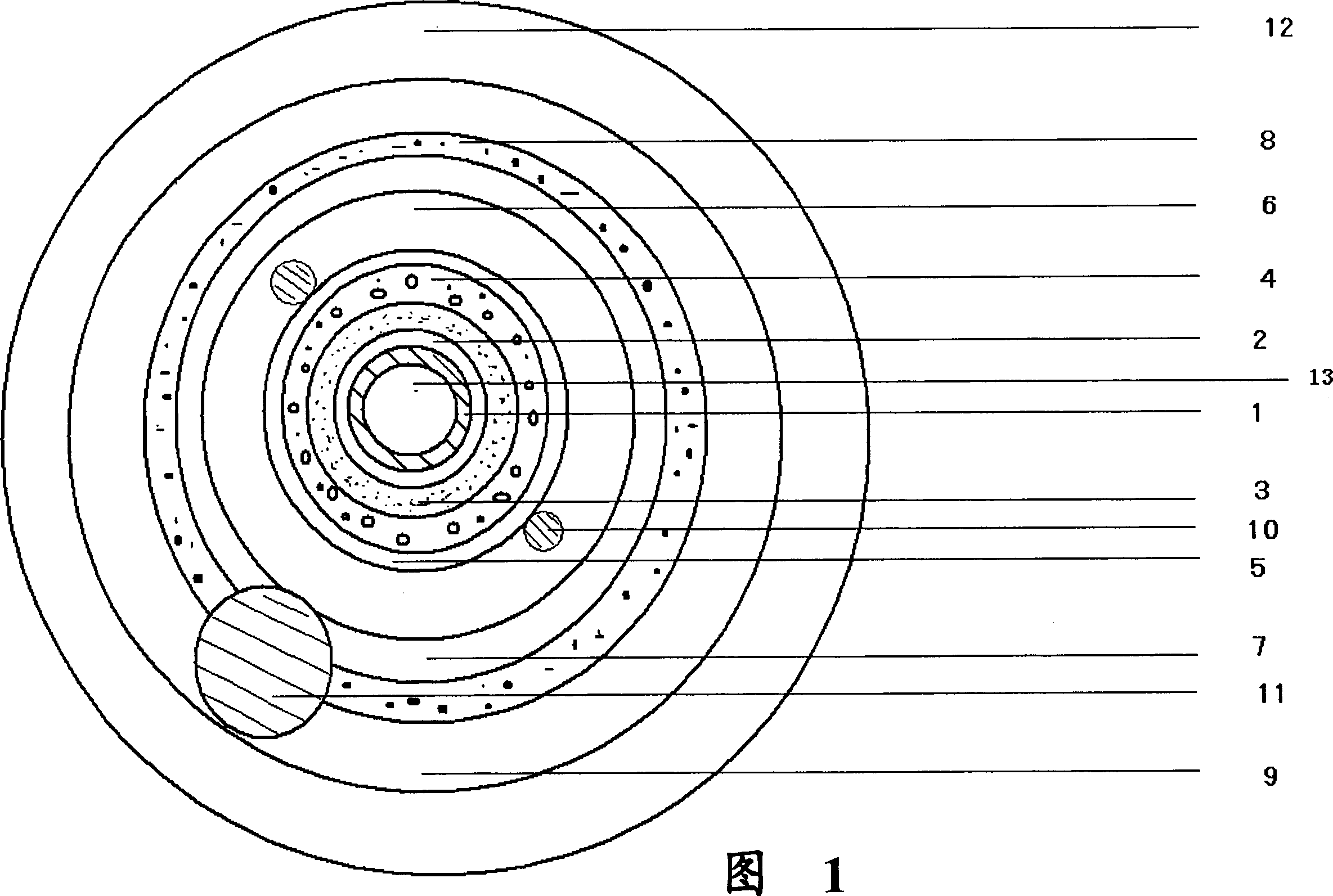
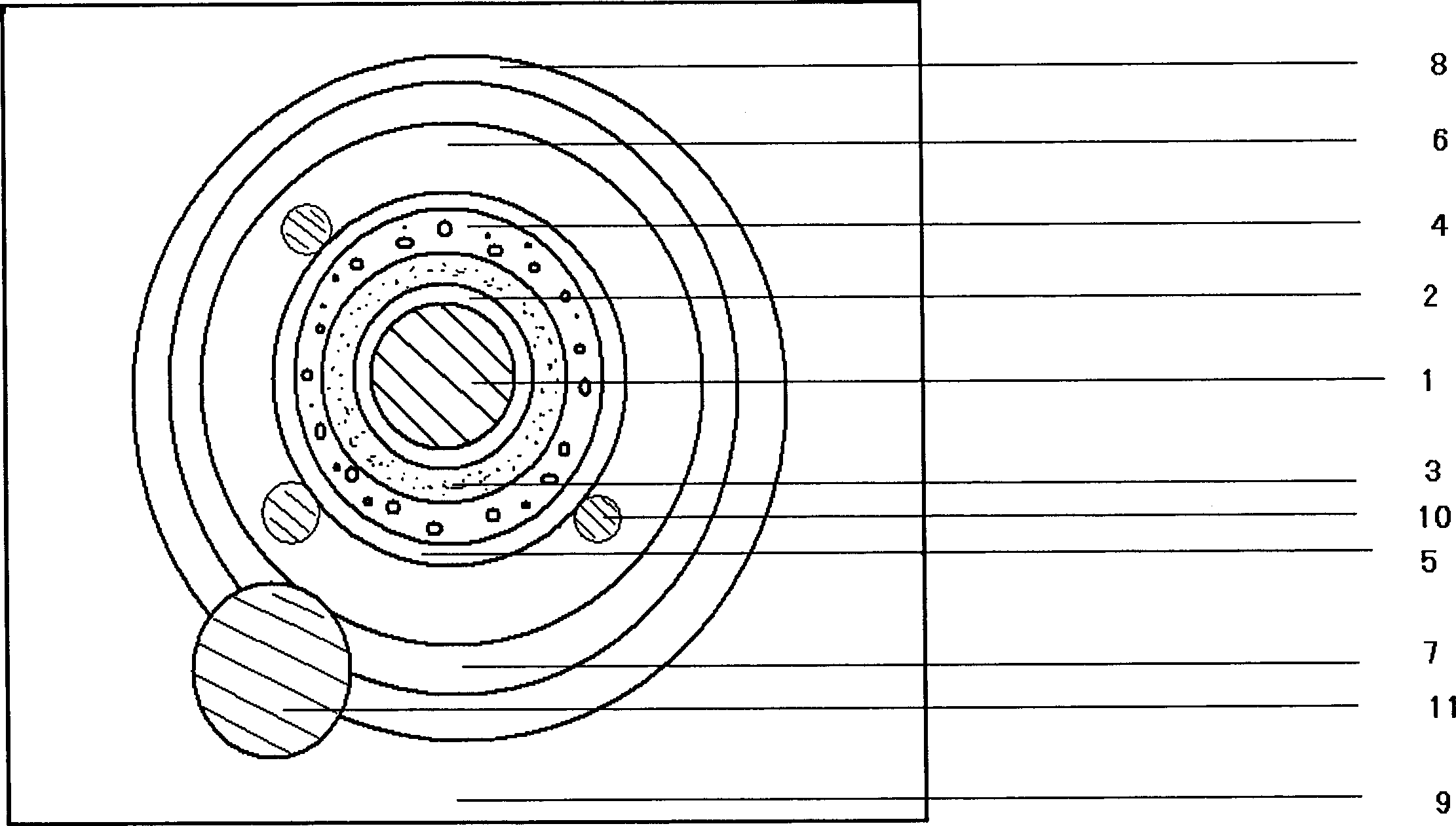
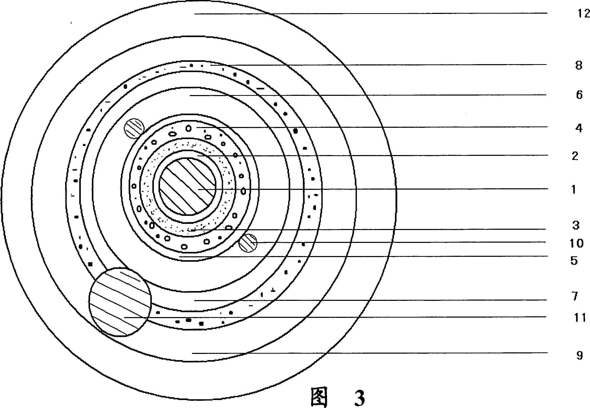
[0048]A continuous baseline body 1 is made of copper wire with a diameter of 0.5 mm. Its surface is coated with a finishing layer 2 of metal Sn. The metal modification layer is coated with a medium layer 3, which is formed by mixing medium slurry and medium powder and applying it uniformly and continuously by wire drawing coating method. The material used for the medium powder is barium titanate, and the main component of the medium slurry is Is: epoxy resin, cyanoethyl sugar, cyanoethyl cellulose, dimethyl formamide diluent, and adding 5% titanium coupling agent (based on the weight of luminescent powder), the weight ratio of medium powder to medium slurry The ratio is 1:1. After coating, the dielectric layer is cured at a temperature lower than 110°C, and the thickness does not exceed 0.2 mm. The luminescent layer 4 is coated with the electroluminescent powder and the luminescent layer slurry by using the brushed coating method. The electroluminescent powder is blue-green Z...

Embodiment 2

[0051] A continuous baseline body 1, whose material is a hollow plastic pipe with a diameter of 1.0 mm. Its surface is plated with a metal Ag modification layer 2 . The metal modification layer is coated with a dielectric layer 3, which is formed by mixing the dielectric slurry and the dielectric powder and applying it uniformly and continuously by wire drawing coating method. The material used for the dielectric powder is a mixture of titanium dioxide and lead titanate, the ratio 1:1, the main components of medium pulp are: epoxy resin, cyanoethyl sugar, cyanoethyl cellulose. Add 7% of silicon-containing coupling agent (based on the weight of luminescent powder), and the weight ratio of medium powder to medium slurry is 1:1. After coating, the medium layer is cured at a temperature lower than 110°C, and the thickness does not exceed 1 mm. . The light-emitting layer 4 is made of blue-green ZnS:Cu electroluminescence powder mixed with 20% YAG light-emitting material, and mixe...

Embodiment 3

[0054] A continuous baseline body 1 is made of copper wire with a diameter of 0.3 mm. Its surface is coated with a metal Sn decoration layer 2 . The metal modification layer is coated with a dielectric layer 3, and the dielectric layer is uniformly and continuously coated by a wire drawing coating method after mixing a dielectric slurry and a dielectric powder. The materials used for the dielectric powder are barium titanate and strontium titanate. Its ratio is 2:1, and the main components of the medium slurry are: epoxy resin, cyanoethyl sugar, cyanoethyl cellulose, dimethylformamide diluent, adding 10% of silane coupling agent (by weight of luminescent powder) . The weight ratio of the medium powder to the medium slurry is 1:1, and the medium layer is solidified at a temperature lower than 110°C after coating, and the thickness does not exceed 1 mm. The luminescent layer 4 is coated with the electroluminescent powder and the luminescent layer slurry by using the drawing co...


PUM

PropertyMeasurementUnit
strengthaaaaaaaaaa
diameteraaaaaaaaaa
particle diameteraaaaaaaaaa

Abstract

The invention consists of a baseline body, a metal decorating layer covering on outside of the baseline body, a dielectric layer covering on the metal decorating layer, a light emitting layer covering on the dielectric layer, a transparent conducting layer covering on the light emitting layer and connected to an out-guard wire. All layers are sealed by fluoroplast.

Description

technical field [0001] The present invention relates to a light-emitting display device in light-emitting physics, in particular to an electroluminescent line that uses an electric field to emit light. Background technique [0002] Linear light-emitting display devices driven by electric energy have been widely used in our life and production. At present, linear light-emitting display devices are mainly realized in two ways: continuous linear light-emitting and dot-matrix combined linear light-emitting. Neon lamps, cold cathode lamps and plastic light made of glass tubes are typical representatives of continuous light-emitting devices, which are characterized by high brightness, rich colors, high power consumption, and one-time molding; dot-matrix combined linear light-emitting devices are mainly neon bulbs Combined with semiconductor light-emitting diodes (LEDs), which are arranged at intervals in a certain direction, they are combined into a linear light-emitting device. ...

Claims


Application Information

Patent Timeline
Patent Type & Authority Applications(China)
IPC IPC(8): H05B33/12H05B33/00H05B33/14
CPCC09K11/7774C09K11/584H01B1/02H01B1/08H01B3/12H05B33/14H05B33/22H05B33/28Y02B20/181Y02B20/00C09K11/7706
Inventor 郑岩
Owner SHANGHAI KERUN PHOSPHOR TECH
Why Eureka
Try Eureka