Plasma method for preparing nano carbon material using coal liquefied residue as raw material

A technology of liquefied residue and plasma torch, which is applied to the chemical characteristics of fibers, textiles and papermaking, etc., can solve problems such as undiscovered, and achieve the effect of easy operation, easy control of parameters, and smooth surface

Inactive Publication Date: 2006-07-26
DALIAN UNIV OF TECH
View PDF0 Cites 56 Cited by
  • Summary
  • Abstract
  • Description
  • Claims
  • Application Information

AI Technical Summary

Problems solved by technology

At present, the main literatures on the utilization of coal direct liquefaction residues include Fuel Processing Technology (2000, 62: 109-118), Sekiran Kagaku Kaigi Happyo Ronbunshu (1998, 35: 427), Clean Coal Technology (2005, (1): 29), Fuel Chemistry Journal (1999, 27 (Supplement): 15-19), etc., but so far, no research report similar or similar to this patented technology has been found in domestic and foreign literature

Method used


Image

  • Plasma method for preparing nano carbon material using coal liquefied residue as raw material
  • Plasma method for preparing nano carbon material using coal liquefied residue as raw material
  • Plasma method for preparing nano carbon material using coal liquefied residue as raw material

Examples


Embodiment 1

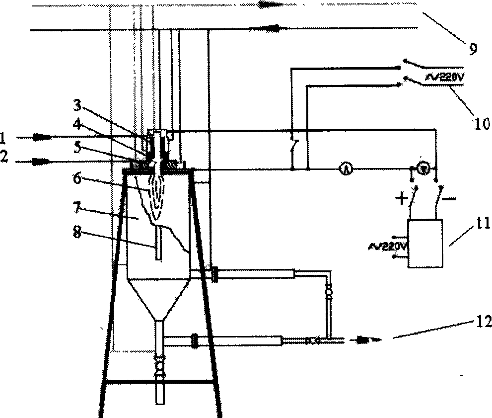
[0027] Put 20g of coal liquefaction residue without any treatment into the crucible and place it 35mm directly below the plasma torch nozzle. Cover the top cover of the reactor, and pass cooling water to the reaction system. Connect the high-frequency voltage power supply and the arc voltage power supply respectively, and then pass in the cathode carrier gas (cooling gas, nitrogen, purity 99.5%) with a flow rate of 4 m 3 / h, anode carrier gas (ionized gas, nitrogen, purity 99.5%) flow rate is 5m 3 / h; Turn on the power supply fan, start the high-frequency power supply to break down the anode ionized gas, ignite the arc, adjust the current to 220-240A, the voltage to 140-150V through the thyristor resistance, and the response time is 150s. After the reaction is over, close the electric, gas and water valves, open the reactor, and take out the product. The obtained product is detected by SEM, HRTEM and EDX, which proves that there are a large number of carbon nanofibers in the...

Embodiment 2

[0029] Put 30g of coal liquefaction residue without any treatment into the crucible and place it 35mm directly below the plasma torch nozzle. Cover the top cover of the reactor, and pass cooling water through the reaction system. Connect the high-frequency voltage power supply and the arc voltage power supply respectively, and then pass in the cathode carrier gas (cooling gas, nitrogen, purity 99.5%) with a flow rate of 4 m 3 / h, anode carrier gas (ionized gas, nitrogen, purity 99.5%) flow rate is 5m 3 / h; Turn on the power supply fan, start the high-frequency power supply to break down the anode ionized gas, ignite the arc, adjust the current to 220-240A and the voltage to 140-150V through the thyristor resistor, and keep the residence time of the reactant under the arc for 165s. After the reaction is over, close the electric, gas and water valves, open the top cover of the reactor, and take out the product. The obtained product is analyzed by SEM, HRTEM and EDX, which prov...


PUM

PropertyMeasurementUnit
diameteraaaaaaaaaa
lengthaaaaaaaaaa
lengthaaaaaaaaaa

Abstract

The invention discloses an arc plasma torch preparing nanometer charcoal fibrous material method, which comprises the following steps: placing untreated leavings of liquefying coal directly in direct current arc plasma torch to carry on heat-treatment; using nitrogen for arc working gas under atmosphere pressure; getting nanometer charcoal fibrous material after 120-175 seconds, wherein there is no need to add in any activators in preparing process. The method is characterized by the following: the craft route is simple; the raw material is the waste of coal hydrogenant liquefaction craft; it's a good way to use coal liquification leavings to prepare high-added value, functional carbon material; the nanometer charcoal fibrous material can be used for accelerating agent, catalyst carrier, lithium ion secondary cell anode material, double-layer capacitor electrode, highly effective active solid, release agent and construction reinforced materials.

Description

technical field [0001] The invention belongs to the scientific and technical field of carbon materials, which is a branch of inorganic non-metallic material science and technology. The invention relates to a method for preparing nano-carbon fiber material by using the direct liquefaction residue of coal as a raw material and adopting an arc plasma torch. Background technique [0002] The characteristic of China's energy resources is that coal resources are abundant, while oil and natural gas are relatively poor, which determines that my country's energy structure must be dominated by coal, and this energy structure will not undergo fundamental changes for a long time in the future. Variety. Today, when the world is facing a severe oil crisis, for the sake of national energy and economic security, coal-to-oil technology has become a major issue that governments and researchers are committed to solving. Since China became a net importer of oil in 1993, its oil imports have gr...

Claims


Application Information

Patent Timeline
Patent Type & Authority Applications(China)
IPC IPC(8): D01F9/127
Inventor 周颖邱介山肖南孙天军赵宗彬
Owner DALIAN UNIV OF TECH
Why Eureka
Try Eureka