
Wafer scale test interface unit and contactors

a technology of interface unit and contactor, which is applied in the field of mixed signal rf, high-speed digital interconnect, shielded dc lines, etc., can solve the problems of large test equipment, large noise, and tendency to smaller pitches, and achieve the lowest loss practical, low insertion loss, and high isolation

Inactive Publication Date: 2019-06-04
CUBIC CORP
View PDF306 Cites 1 Cited by
  • Summary
  • Abstract
  • Description
  • Claims
  • Application Information

AI Technical Summary

Benefits of technology

The patent describes a new design for a 3D coax structure that can be used in high-speed digital and RF transmission lines. The structure has a low loss and can handle high-speed signals. It also provides optimal isolation between adjacent signal lines and can mitigate the effects of DC line noise. The structure can be used in test interface units for wafer-level or multi-device testing. The 3D coax design allows for many more mating cycles to chips and wafer electrical contact points than traditional probe card connections. The structure also allows for more dense routing requirements and can include various passive components to process or condition RF signals before routing to an external connection. Overall, the 3D coax structure provides a better solution for high-speed digital and RF transmission lines.

Problems solved by technology

A somewhat similar problem occurs in testing integrated circuit devices where the test electronics and the pitch of the bond pads or solder bumps on the chip or multi-chip module (MCM) are quite small, the test equipment is large, and particularly at frequencies and data rates increasing, for example approaching 10's or 100 Gb / s.
In wafer die testing, as the communications chips on wafers require increasing frequency RF testing, and complex circuit testing, to determine pass / fail criteria before being sold, the industry faces a challenge to route input and output RF test signals as well as DC feed lines on 2D pitches where pads may be spaced on 0.5 mm spacing, but continue to trend to smaller pitches which are ultimately limited by the ability to test pads or solder bumps on the desired spacing.
As integrated circuits are built with more transistors and operate at higher clock rate frequencies, much more noise is induced by the simultaneous switching action of millions or billions of transistors on the chip processing the data operations.
This noise is coupled onto the DC power and ground supplies and can affect performance, especially bit error rate performance.

Method used


Image

  • Wafer scale test interface unit and contactors
  • Wafer scale test interface unit and contactors
  • Wafer scale test interface unit and contactors

Examples


Embodiment Construction

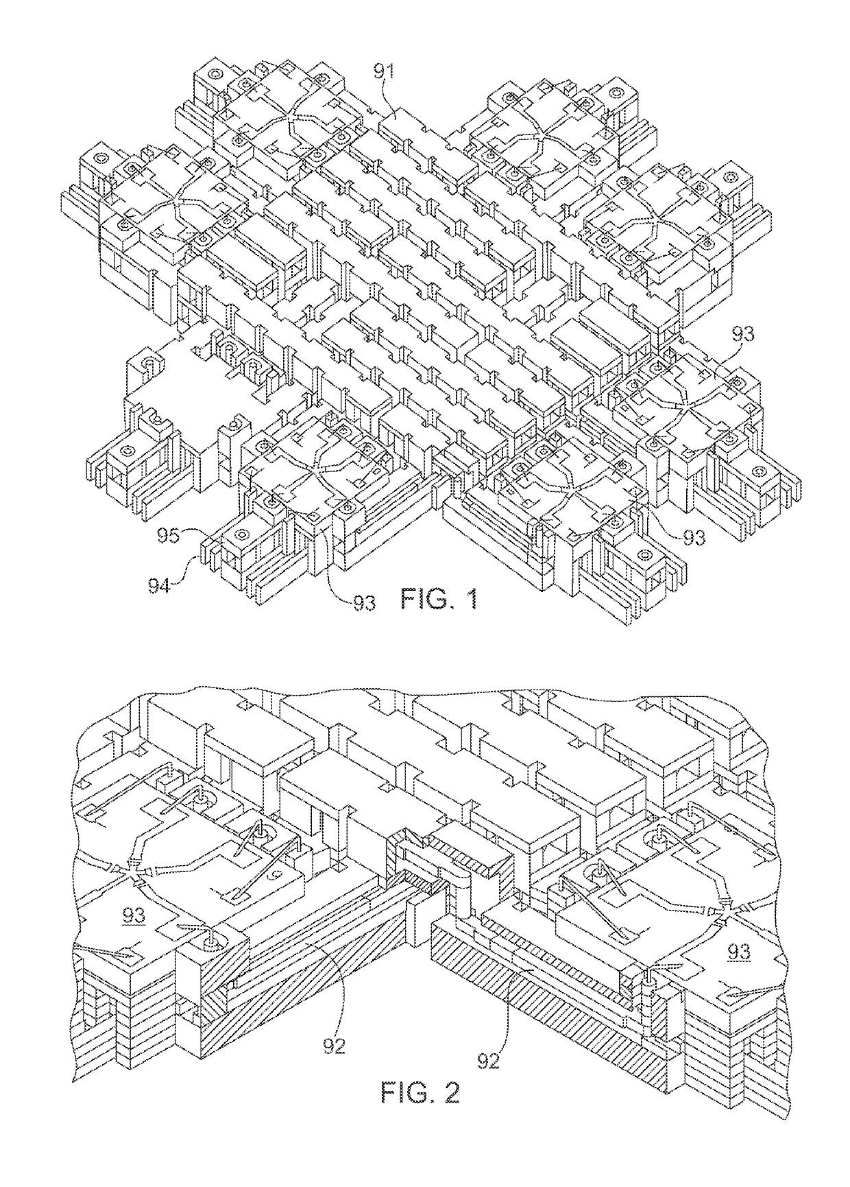
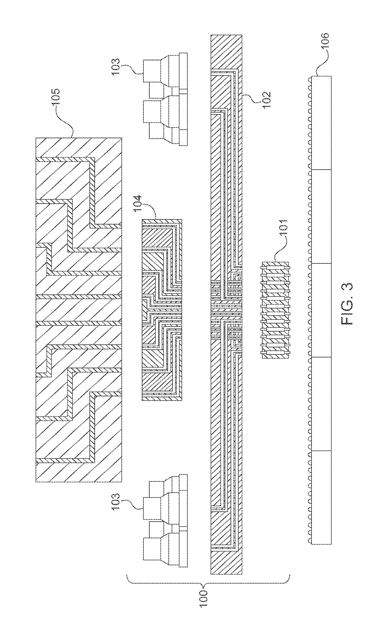
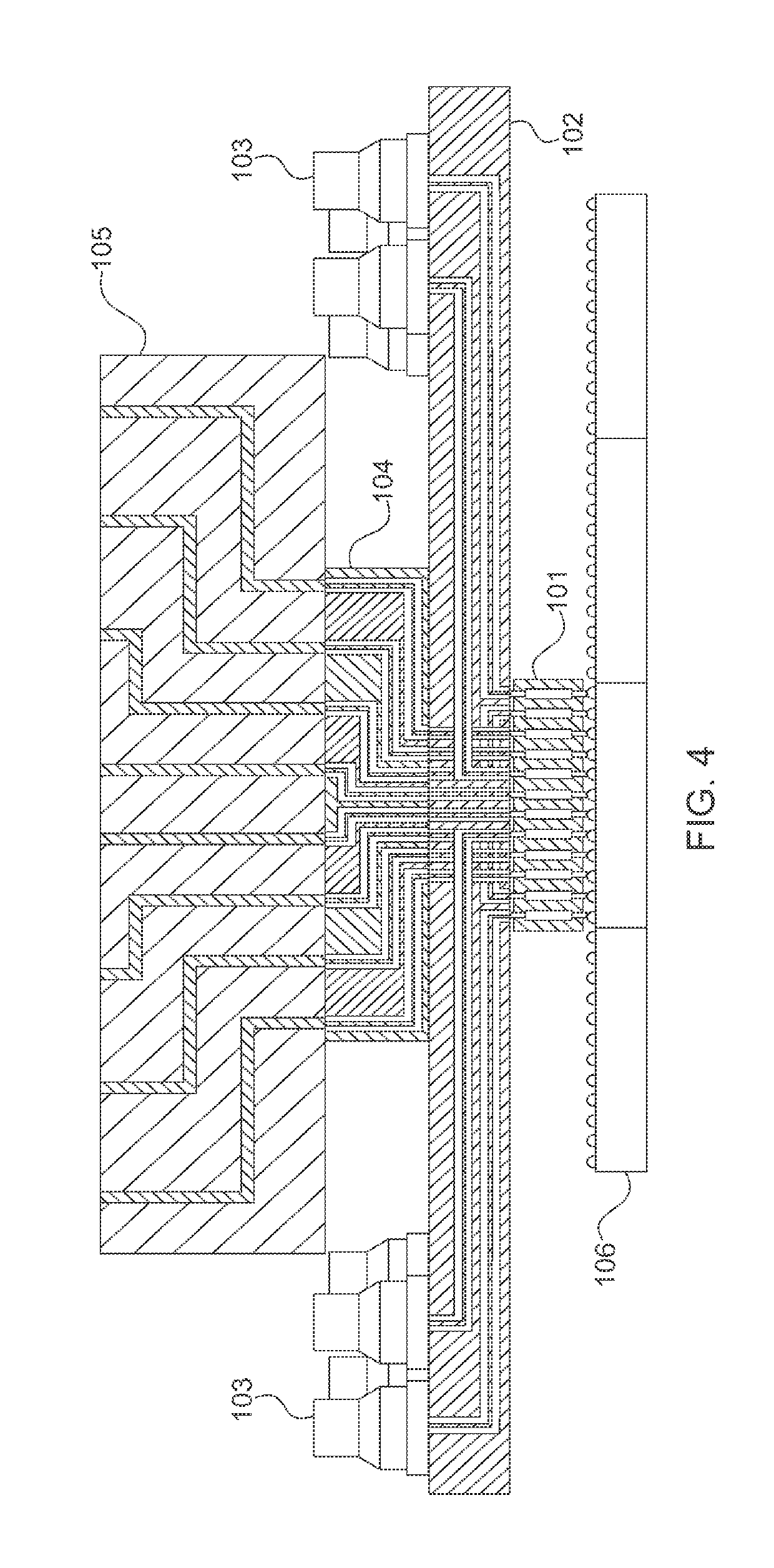
[0051]Referring now to the figures, wherein like elements are numbered alike throughout, FIGS. 3-4 schematically illustrate an exemplary configuration of a wafer level test interface unit 100 in accordance with the present invention for use in testing a device under test (DUT) 106. The wafer level test interface unit 100 may be configured to provide repeated testing of multiple devices under test 106, especially at the grid / wafer level, while overcoming numerous problems in the existing art. For example, typically, the device under test 106 will include RF and DC circuitry, which is typically tested through the use of a probe card assembly comprised of printed circuit boards 105 and a contactor array 101. (The printed circuit board 105 can represent a non-coaxial printed circuit card where processing or interfacing with active and passive components can be conducted close to the device under test 106.) However, the pitch of features on the device under test 106 is most often much fi...


PUM


Abstract

Devices and methods for multilayer packages, antenna array feeds, test interface units, connectors, contactors, and large format substrates. The device comprising a 3D coaxial distribution network structure including a plurality of coaxial transmission lines separated by a first pitch at the input and a second, wider pitch at the output thereof.

Description

RELATED APPLICATIONS[0001]This application is a 371 application of International Application No. PCT / US2015 / 011789 filed Jan. 16, 2015, which claims the benefit of priority of U.S. Provisional Application No. 61 / 928,767 filed on Jan. 17, 2014, the entire contents of which application(s) are incorporated herein by reference.FIELD OF THE INVENTION[0002]The present invention relates generally to mixed signal RF, high speed digital interconnects, shielded DC lines, and more particularity, but not exclusively, to their implementation for multilayer packages, antenna array feeds, test interface units, connectors, contactors, and large format substrates, including methods for their fabrication.BACKGROUND OF THE INVENTION[0003]Printed Circuit Boards (PCB) are the current mainstay for virtually all integrated circuit assembly and packaging today for computers, laptops, cell phones, cameras, TVs, appliances, avionics, etc. However new high speed and high density circuit technologies are emerg...

Claims


Application Information

Patent Timeline
Patent Type & Authority Patents(United States)
IPC IPC(8): G01R31/28G01R1/073G01R1/067
CPCG01R31/2889G01R1/06716G01R1/07307G01R1/06722G01R1/07357G01R1/0491G01R1/07378H01Q1/2283H01Q21/0006H01Q21/0093H01Q21/065
Inventor THOMPSON, RICK L.VANHILLE, KENNETHBORYSSENKO, ANATOLIY O.ROLLIN, JEAN MARC
Owner CUBIC CORP
Learn More