In-situ injection of soil and groundwater—high pressure rotary jet grouting in-situ remediation system and method

a soil and groundwater remediation and in-situ injection technology, which is applied in the direction of drilling pipes, contaminated groundwater/leachate treatment, water/sewage treatment by oxidation, etc., can solve the problemsthreatening the environment and human health and safety, and destroying the ecological environment. it is easy to achieve the effect of destroying the bearing capacity of the foundation, and reducing the risk of contamination

Active Publication Date: 2020-09-29
BCEG ENVIRONMENTAL REMEDIATION CO LTD
View PDF12 Cites 0 Cited by
  • Summary
  • Abstract
  • Description
  • Claims
  • Application Information

AI Technical Summary

Benefits of technology

[0027]1. The remediation system is simple in design, small in equipment, and easy to move. It is superior to complex designs or special equipment such as necessary exhaust or wastewater system required for other technologies such as in-situ heating, thermal desorption or soil leaching. The remediation costs are lower than that for situ heating, thermal desorption and other technologies. The remediation efficiency of the in-situ system and the removal of contaminants may be optimally achieved.
[0028]2. Compared with a single tube injection method such as a high pressure injection of a drill bit (e.g., Geoprobe drill) or a Chemgrout grouting method, the present invention adopts a gas and liquid double tube high pressure injection process, which on the one hand has a high injection pressure (25˜30 Mpa). However, at present, the maximum pressure of the drill bit injection is only 18 Mpa, and the injection pressure is small, the diffusion radius of the remediation agent is relatively small and the diffusion is uneven, in addition, slurry-return for the single tube injection is more serious when encountering shallow groundwater remediation sites. On the other hand, the effect of the high-pressure air flow in the process of injecting the remediation agent fluid significantly increases the diffusion effect of the remediation agent in the soil and groundwater environment, and the diffusion radius increases remarkably. The formation suitable for high-pressure injection of the drill bit has a small amount. For low-permeability formation injection, due to insufficient pressure and single-tube operation, it is easy to form preferential fracturing channels and the injection efficiency is low. Further, the drill bit injection system has a problem of low injection efficiency due to the small flow rate of the configured grouting pump. Therefore, the present invention may overcome the defects of small diffusion radius, serious slurry return and low injection efficiency in the single tube injection method of the drill bit.
[0029]3. Compared with the well construction injection technology, the application range of the present invention has been greatly expanded. The prior art is only applicable to medium to high permeability formations (such as fine sand, medium coarse sand, etc.), while the technical application of the present invention may be extended to low to medium permeability formations (e.g., silty clay, silt, silty clay, clay layers). Injection well technology is only suitable for non-saturated layers or sites with deep groundwater levels due to the small injection pressure, while the present invention may be applied to the pollution for single soil, the pollution for groundwater combined with soil (saturated layer), the pollution for single groundwater, etc., and may solve the problem of maximum grouting amount and slurry return in the in-situ injection process, and greatly improve the injection efficiency. At the same time, the present invention is better than the injection well in linear-meter-controlling the injection parameters of the drug according to the depth, so that the demand for optimizing agent dosage parameters by depth partition in treatment of soil and groundwater in large and complex contaminated sites may be achieved. The present invention replaces the injection well by means of injection point (drilling) so as to one the one hand save the cost of well construction, and on the other hand to put into use immediately without cleaning up the sites after the construction of agent injection due to the absence of waste equipments such as PVC wells in the sites after remediation. In the present invention, the injection amount for each linear meter per hole is large. Generally, a round of injection (using a double spray process if necessary) may meet the engineering design needs. The agents for injection well are dosed with intermittent multiple injections. Thus, the injection well remediation method has a relatively long remediation cycle.
[0030]4. By using the present invention, a pneumatic percussion rotary drilling method is used in the hole guiding stage, while large-scale contaminated sites need a certain period of time to build wells in terms of the well construction of the injection wells using the US Geoprobe rigs or domestic geological rigs (such as 30 rigs, car rigs, etc.) where the rotary or percussion drilling methods are often used. The introduction of air flow during the drilling process on the one hand improves the construction efficiency and reduces the cost. On the other hand, the introduction of the air flow is beneficial to open the soil pores of the mixed fill layer, and provides favorable conditions for the uniform diffusion of the agent for injecting the unsaturated layer in the later period. The method of guiding the hole has lower costs and provides time guarantee for the subsequent in-situ injection—continuous construction of the high pressure rotary jet grouting operation.
[0032]6. Being equivalent to stirring technology, such as hot air blowing deep layer mixing, the remediation method is performed top-down, may not solve the remediation problem of the sandwich layer. The present invention adopts fixed depth injection remediation, which may solve defects and contradictions such as disturbing the upper non-polluting part by the mixing technology, causing serious secondary pollution and destroying bearing capacity of the foundation. At the same time, the energy consumption of mechanical agitation is much larger than the energy consumption of the equipment for effectively diffusing the airflow and the liquid flow in the present invention. The fixed depth remediation solves the problem of soil and groundwater remediation in the sandwich layer, and maintains the original bearing capacity after construction, in particular, it has economic advantages in the remediation of sand soil and groundwater and is significant in highly efficient construction.

Problems solved by technology

In recent years, with the global industrialization process, China's soil contamination has become increasingly serious.
Among them, organic contamination and heavy metal contamination have become two important types of contamination, which not only damage the ecological environment itself, but also directly or indirectly endanger the environment and human health and safety.
More seriously, volatile and semi-volatile organic contaminants and soluble heavy metals may migrate to deep saturated regions (aquifers) in unsaturated regions (aeration zones), especially resulting in a menace to groundwater resources, causing serious consequences.
Due to factors such as diversification of remediation media in contaminated sites (soil and water combined pollution, individual soil contamination, individual groundwater contamination), complexity of hydrogeological conditions, diversity of pollution types (organic contamination heavy metals, etc.), particularity of contaminants and uneven distribution and difference in soil and groundwater, the difficulty and challenge of in situ remediation of soil and groundwater has been determined.
The agitation drill bit employed is an integrated impeller bit, so the mixing depth is limited and the resistance is large.
The application has certain limitations and is only suitable for the treatment of looser formations.
Application No. 201510159423.2, “Chromium contamination in-situ remediation method”, Chinese invention patent, mentioning a Geoprobe high-pressure injection method and distribution method (the highest pressure is only 18 Mpa, it is essentially a single tube injection; the disadvantage is that the construction efficiency is low and it is difficult to meet the engineering application), does not consider the flow of groundwater and the diffusion factor of the agent.
On the one hand, the construction cost for the well is relatively high, and it is necessary to construct a large number of injection wells.
The capital construction cost is high and the construction period is long.
On the other hand, the injection pressure is insufficient (using natural flow or low pressure injection), and the formation conditions have a great influence on the injection effect.
If the clay layer or formation properties are not uniform, the agent cannot spread evenly, affecting the remediation effect and even failing to complete the remediation.
The saturated layer soil is difficult to grout, the diffusion radius is small, and the applicable formation is limited, and the clay layer almost loses its diffusion effect.
Large-scale contaminated sites require a certain period of time to construct wells.

Method used


Image

  • In-situ injection of soil and groundwater—high pressure rotary jet grouting in-situ remediation system and method
  • In-situ injection of soil and groundwater—high pressure rotary jet grouting in-situ remediation system and method
  • In-situ injection of soil and groundwater—high pressure rotary jet grouting in-situ remediation system and method

Examples


embodiment 1

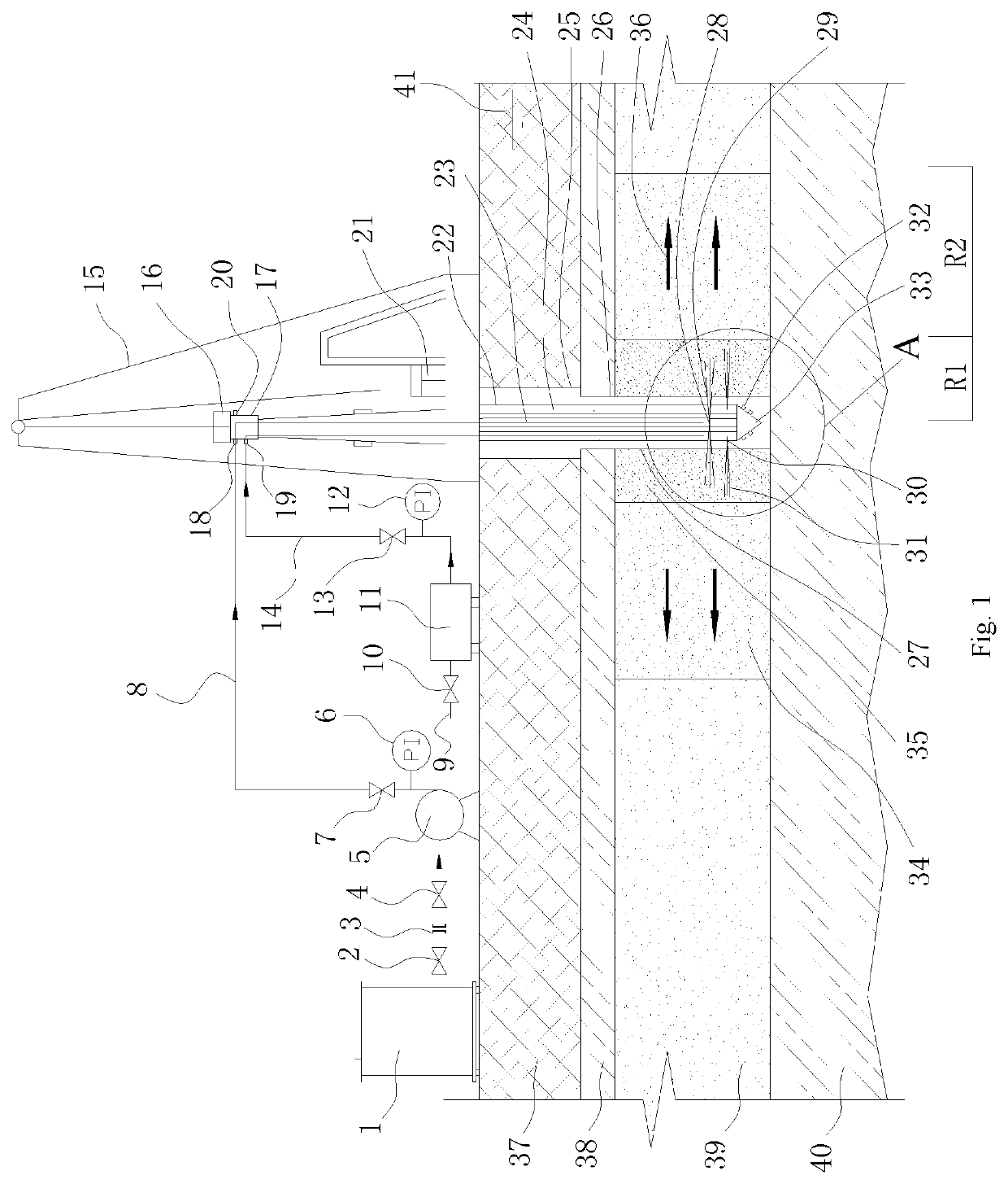
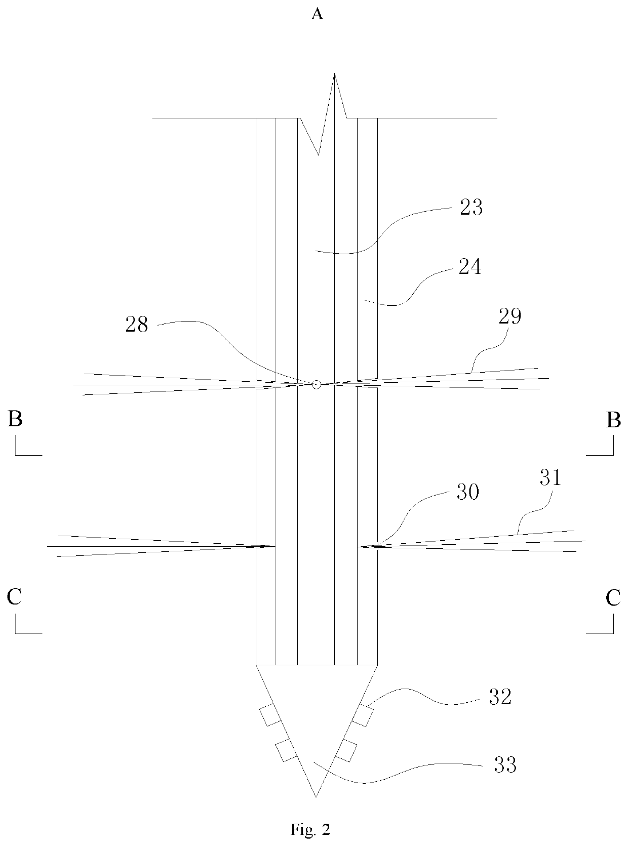
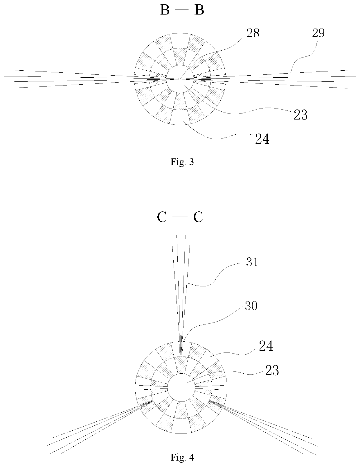
[0050]The project is a soil and groundwater remediation project of a chemical plant in Nanjing. The amount of soil remediation works is 258000 square meters, the amount of groundwater remediation works is 170000 square meters, and the construction period requires 150 days. The maximum remediation depth of the soil in this site is 12 m. There are two layers of silty clay layer and the aquifer is fine sand layer (distributed at 3˜6 m or 4˜7 m). The groundwater is shallow (about 1 m) and rich. The target contaminants in soil and groundwater are VOCs / SVOCs organic substances such as chlorobenzene, benzene, and p / o-nitrochlorobenzene. The remediation medium is divided into two types: combined pollution of soil and groundwater, and separate contamination areas of groundwater. In the early stage, the test work of injecting oxidant into the injection well was used, which has the disadvantages of high cost, small diffusion radius, being unsuitable for injection of silty clay layer and satura...


PUM

PropertyMeasurementUnit
air pressureaaaaaaaaaa
depthaaaaaaaaaa
aperture diameteraaaaaaaaaa

Abstract

An in-situ injection of soil and groundwater—high pressure rotary jet grouting in-situ remediation system and method. The system has an agent dispensing station, high pressure grouting pump, air compressor, rotary jet grouting drilling machine, second double-pipe water flow joint, automatic lifting mechanism for grouting drill pipe of rotary jet grouting drilling machine, high pressure jet drill pipe, inner tube for high pressure jet triple drill pipe, outer tube for high pressure jet triple drill pipe, agent jet nozzle, an air jet nozzle, cemented carbide block and a drill bit. Parameters are arranged according to the triangle method to ensure that the remediation area is covered within the diffusion radius of the agent. After positioning the GPS measuring point, a guided-boring rig is positioned at the center of the injection point. The high pressure injection remediation uses a double-pipe: using gas and liquid fluids to spread the soil while cutting the soil from bottom to top to achieve thorough mixing of the remediation agent with soil and groundwater; quickly combining laboratory testing to obtain parameters for remediation agent residues, pH values, and contaminant concentrations to verify the in-situ remediation effect and monitor the residual agent.

Description

TECHNICAL FIELD[0001]The present invention relates to an in-situ injection of soil and groundwater—high pressure jet grouting in situ remediation method, belongs to the technical field of soil and groundwater in situ remediation system and remediation method.BACKGROUND TECHNOLOGY[0002]Soil and groundwater environments are an important part of the ecosystem. In recent years, with the global industrialization process, China's soil contamination has become increasingly serious. Among them, organic contamination and heavy metal contamination have become two important types of contamination, which not only damage the ecological environment itself, but also directly or indirectly endanger the environment and human health and safety. More seriously, volatile and semi-volatile organic contaminants and soluble heavy metals may migrate to deep saturated regions (aquifers) in unsaturated regions (aeration zones), especially resulting in a menace to groundwater resources, causing serious conseq...

Claims


Application Information

Patent Timeline
Patent Type & Authority Patents(United States)
IPC IPC(8): B09C1/00E21B7/18E21B17/18C02F1/72B09C1/08
CPCB09C1/08C02F1/72E21B7/18E21B17/18B09C2101/00C02F1/74C02F2103/06C02F1/686C02F1/70C02F1/50
Inventor LI, SHUPENGYANG, YUEWEIGUO, LILILIU, PENGZHANG, YUESONG, XIAOWEICHEN, FANYIN, PENGCHENGWANG, FUWANGLIU, YANNIU, QIANGBU, FANYANG
Owner BCEG ENVIRONMENTAL REMEDIATION CO LTD
Why Eureka
Try Eureka